CME-12B32 AXIOM, CME-12B32 Datasheet - Page 13
CME-12B32
Manufacturer Part Number
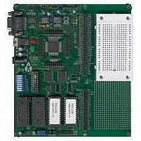
CME-12B32
Description
Microprocessor Development Tool
Manufacturer
AXIOM
Datasheet
1.CME-12B32.pdf
(15 pages)
Specifications of CME-12B32
Silicon Manufacturer
Freescale
Kit Contents
Board
Silicon Core Number
68HC12B32
Memory Organization - Flash
32 KB
Development Tool Type
Hardware - Eval/Demo Board
Clock Frequency
16MHz
Lead Free Status / RoHS Status
Contains lead / RoHS non-compliant


KEYPAD
LCD_PORT
The LCD_PORT interface is connected to the data bus and memory mapped to locations 270 and 271 hex in the
register following area (see Memory Map). Address 270 is the Command register, address 271 is the Data register.
The interface supports all OPTREX
the most common pinout for a dual row rear mounted display connector. Power, ground, and Vee are also
available at the LCDPORT-1 connector.
DEBUG
The DEBUG port is a 6 pin header compatible in pinout with the Motorola Background Debug Mode (BDM) Pod.
This allows the connection of a background debugger for software development, programming and debugging in
real-time, since the BDM control logic does not reside in the CPU.
A Background Debug Module is available from the manufacturer. Contact Axiom Manufacturing for more
information.
BGND
1
2
3
4
5
6
7
8
LCD1
LCD3
+5V
D11
D13
D15
D9
A0
PS4
PS5
PS6
PS7
PP4
PP5
PP6
PP7
1 2
3 4
5 6
10
12 11
14 13
2
4
6
8
2
4
1
3
5
7
9
1
3
GND
/RESET
+5V
The KEYPAD connector is a passive 8-pin connector that can be used to connect a 4 x
4 matrix (16 key) keypad device. The connector is mapped to the HC12 I/O ports S and
P. This interface is implemented as a software keyscan. Pins PS4-7 are used as
column drivers which are active low outputs. Pins PP4-7 are used for row input and
provide an idle hi condition with internal pull-ups to provide active key detection under
software control.
See the HC12 Technical Reference Manual and sample source code for a full
description of these pins and how to configure and use these ports.
See the program KEYPAD.ASM for an example of using this port.
GND
LCD-Vee
/RW
D8
D10
D12
D14
LCD2
LCD4
See the HC12 Technical Reference Manual for complete documentation
of the BDM.
Command Register:
Data Register:
LCD-Vee is supplied by U13 and is adjusted by the R18 Potentiometer
(adjustable resistor).
See the file KEYLCD.ASM for an example program using this LCD connector.
Additional lines can be used as enables for larger panels and are mapped as:
LCD2
LCD3
DMC series displays in 8 bit bus mode with up to 80 characters and provides
= $274 & $275
= $278 & $279
13
$270
$271
LCD4
= $27C & $27D
Related parts for CME-12B32
Image
Part Number
Description
Manufacturer
Datasheet
Request
R


Part Number:
Description:
Microprocessor Development Tool
Manufacturer:
AXIOM
Datasheet:

Part Number:
Description:
CMD-5XX MOTHERBOARD ONLY
Manufacturer:
AXIOM
Datasheet:
