CMD-711EX AXIOM, CMD-711EX Datasheet
CMD-711EX
Specifications of CMD-711EX


Related parts for CMD-711EX


CMD-711EX Summary of contents
Page 1
... Lingco Dr., Suite 209 CMD711-EX Development Board Richardson, TX 75081 (972) 994-9676 FAX (972) 994-9170 email: Gary@axman.com web: http://www.axman.com ...
Page 2
GETTING STARTED ...................................................................................................... 3 DEVELOPMENT PHILOSOPHY .......................................................................... 3 SOFTWARE.................................................................................................................... 4 TUTORIAL ...................................................................................................................... 4 C REATING SOURCE CODE U P SING THE ROGRAMMING Programming the External EEPROM.............................................................................. 5 Programming Internal EPROM ....................................................................................... 6 USING THE BUFFALO MONITOR................................................................................. 6 MEMORY MAP ............................................................................................................... ...
Page 3
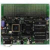
... The Axiom CMD711-EX single board computer is a fully assembled, fully functional development system for the Motorola 68HC11E Microcontroller series, complete with wall plug style power supply and serial cable. To get started quickly, perform the following test now to make sure everything is working correctly: 1 ...
Page 4
... See the README file for a complete listing of all programs and files on the disk. TUTORIAL This section should help you get started with the specifics of the CMD711-EX development process. Be sure to read the rest of this manual as well as the documentation on the disk if you need further information. ...
Page 5
For this tutorial we'll use a sample assembly language program in the EXAMPLES sub-directory called HELLO.ASM. This small program sends a text string to your PC serial port you haven’t done so already, verify that the development board ...
Page 6
... Internal Program Memory in step 5. This will put your program in the EPROM on the microcontroller. This may be either in OTP form or UV erasable (windowed) form. NOTE: A programming adapter can be purchased from Axiom Mfg. to provide programming for different 68HC11 package styles or for easier insertion and removal. ...
Page 7
MEMORY MAP Following is the DEFAULT EXPANDED MODE memory map for this development board identical to the HC11 E series memory maps shown in section 4 of the technical data book. See this section for other non-expanded modes ...
Page 8
ADDRESS DECODING sockets and hold 32k RAM chips for external data storage and for debugging programs. accommodate EEPROM or ROM but is primarily used for program storage using an EEPROM. Jumpers JP1 through JP7 and Mode Switches ...
Page 9
... Power requirement Programming Voltage Devices Supported MC68HC11E0FN MC68HC11E1FN MC68HC711E9FN / FS MC68HC11E20FN MC68HC711EA9FN / FS Additional devices supported with optional adapters. Contact Axiom Mfg. for availability. COM1 9.8304 MHz 2.4576 MHz 0°C to +70°C Nominal 9V +25V @ 100 ma. +12V @ 30 ma. supplied with mode switch 8 ON MC68HC11E8FN ...
Page 10
JUMPERS AND SWITCHES ON enables A13 to U3. Normally this should never be removed, except when using an 8K JP1 device in U3. JP2 ON enables A14 to pin (RAM or EEPROM) JP3 ON enables A14 to ...
Page 11
SERIAL PORT The onboard serial port COM1 is a simple, three wire asynchronous serial interface with hard wired Clear to Send (CTS) and Data Terminal Ready (DTR driven by the HC11 internal SCI port using I/O pins PD0 ...
Page 12
This set of 4, 14-pin connectors can be used to connect an external Programming Adapter or an Emulator Interface to the board. See the Technical Data Book for detailed information on all of these lines. P1 XTAL ...
Page 13
I/O POINTS The following connector points on the board do not have connectors attached but are provided for easy access. COM1 Points These points located next to the DB-9 serial port connector COM1, can ...
Page 14
... TROUBLESHOOTING TROUBLESHOOTING The CMD711-EX board is fully tested and operational before shipping fails to function properly, inspect the board for obvious physical damage first. Ensure that all socketed IC devices are properly seated in the their sockets. Verify that your PC communications port is working by substituting a known good serial device doing a loop back diagnostic ...
Page 15
Tips and Suggestions Following are a number of tips, suggestions and answers to common questions that will solve most problems users have with the AX11E development system. Troubleshooting, which will have the most complete and updated information. There also may ...