CME12BC32 AXIOM, CME12BC32 Datasheet - Page 10
CME12BC32
Manufacturer Part Number
CME12BC32
Description
Microprocessor Development Tool
Manufacturer
AXIOM
Datasheet
1.CME12BC32.pdf
(18 pages)
Specifications of CME12BC32
Silicon Manufacturer
Freescale
Core Architecture
HC12
Kit Contents
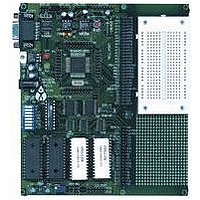
Development Board With 64K SRAM And 32K Flash
Silicon Family Name
HC12
Silicon Core Number
68HC12BC32, 68HC12B32
Lead Free Status / RoHS Status
Contains lead / RoHS non-compliant


The CME-12B/BC board is shipped from the manufacturer with the following default CONFIG
SWITCH settings:
The 8 position CONFIG SWITCH provides an easy method of configuring the CME-12B/BC32
board operation.
usage:
MEM-SEL JUMPERS
Memory sockets U4/5 are shipped with 32K byte RAM devices. U6/7 are shipped with 32K
byte EPROM devices programmed with the D-bug12 monitor.
1,3,4
1,3
2,4
(1)
on for proper operation.
(2)
SWITCH position 3 is also on. When in off position memory space is SRAM for BDM
use.
ON
SWITCH
CONFIG
1
Enables monitor EPROM’s in memory map at 0x8000 – FFFF hex if CONFIG
Enables memory bus operation for access to board memory. Expanded bus must be
1
2
3
4
5
6
7
8
MODE CHART
Single Chip Mode
Expanded Wide Mode
IN: enables RAM or EEPROM, 32K devices to U6/7
IN: enables RAM or EEPROM, 8K devices in U6/7
IN: enables EPROM, 8K or 32K devices in U6/7 (Default)
ON
2
MODE A selection (see Mode chart
below)
MODE B selection (see Mode chart
below)
EXT –External Memory enable
MON –Monitor Memory enable
VPP - Flash VPP voltage enable
RXD - Serial Port RXD input enable
PC0 –CAN Port RXCAN enable
PC1 –CAN Port TX enable
Following are the configuration switch descriptions and HC12 I/O port
ON
3
OPERATION when in ON position
ON
4
OFF
5
A and B = OFF
A and B = ON
ON
6
10
OFF
7
(1)
(2)
OFF
8
HC12 I/O PORT USED
MODA / PE5
MODB / PE6
PS0 / RXD
PC0
PC2
N/A
N/A
N/A
Related parts for CME12BC32
Image
Part Number
Description
Manufacturer
Datasheet
Request
R


Part Number:
Description:
Microprocessor Development Tool
Manufacturer:
AXIOM
Datasheet:

Part Number:
Description:
Microprocessor Development Tool
Manufacturer:
AXIOM
Datasheet:

Part Number:
Description:
CMD-5XX MOTHERBOARD ONLY
Manufacturer:
AXIOM
Datasheet:
