MC-NOVE MULTICOMP, MC-NOVE Datasheet - Page 2
MC-NOVE
Manufacturer Part Number
MC-NOVE
Description
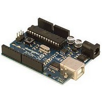
Arduino Duemilanove Based Board W/ ATMEGA328
Manufacturer
MULTICOMP
Datasheet
1.MC-NOVE.pdf
(4 pages)
Specifications of MC-NOVE
Silicon Manufacturer
Atmel
Core Architecture
AVR
Features
16MHz Crystal Oscillator, USB Connection, ICSP Header
Kit Contents
Development Board Only
Silicon Family Name
Atmega
Lead Free Status / RoHS Status
Lead free / RoHS Compliant


The power pins are as follows:
•
•
•
•
Memory
The ATmega328 has 32 KB of flash memory for storing code (of which 2 KB is used for the bootloader) The ATmega328 has 2 KB
of SRAM and 1 KB of EEPROM (which can be read and written with the EEPROM library).
Input and Output
Each of the 14 digital pins on the MC-NOVE can be used as an input or output, using pinMode(), digitalWrite(), and digitalRead()
functions. They operate at 5 volts. Each pin can provide or receive a maximum of 40 mA and has an internal pull-up resistor
(disconnected by default) of 20-50 kOhms. In addition, some pins have specialized functions:
•
•
•
•
•
The MC-NOVE has 6 analog inputs, each of which provides 10 bits of resolution (i.e. 1024 different values). By default they
measure from ground to 5 volts, though is it possible to change the upper end of their range using the AREF pin and the
analogReference() function. Additionally, some pins have specialized functionality:
•
There are a couple of other pins on the board:
•
•
Communication
The MC-NOVE has a number of facilities for communicating with a computer, another Arduino™, or other microcontrollers. The
ATmega328 provide UART TTL (5V) serial communication, which is available on digital pins 0 (RX) and 1 (TX). An FTDI FT232RL
on the board channels this serial communication over USB and the FTDI drivers (included with the Arduino™ software) provide a
virtual com port to software on the computer. The Arduino™ software includes a serial monitor which allows simple textual data to
be sent to and from the board. The RX and TX LEDs on the board will flash when data is being transmitted via the FTDI chip and
USB connection to the computer (but not for serial communication on pins 0 and 1).
A SoftwareSerial library allows for serial communication on any of the MC-NOVEs digital pins.
The ATmega328 also support I2C (TWI) and SPI communication. The Arduino™ software includes a Wire library to simplify use of
the I2C bus; see the documentation for details. To use the SPI communication, please see the ATmega328 datasheet.
MC-NOVE
Arduino™ Duemilanove Compatible Development Board
http://www.farnell.com
http://www.newark.com
http://www.cpc.co.uk
VIN. The input voltage to the board when it's using an external power source (as opposed to 5 volts from the USB
connection or other regulated power source). You can supply voltage through this pin, or, if supplying voltage via
the power jack, access it through this pin.
5V. The regulated power supply used to power the microcontroller and other components on the board. This can
come either from VIN via an on-board regulator, or be supplied by USB or another regulated 5V supply
3V3. A 3.3 volt supply generated by the on-board FTDI chip. Maximum current draw is 50mA.
GND. Ground pins.
Serial: 0 (RX) and 1 (TX). Used to receive (RX) and transmit (TX) TTL serial data. These pins are connected to the
corresponding pins of the FTDI USB-to-TTL Serial chip.
External Interrupts: 2 and 3. These pins can be configured to trigger an interrupt on a low value, a rising or falling edge, or
a change in value. See the attachInterrupt() function for details.
PWM: 3, 5, 6, 9, 10, and 11. Provide 8-bit PWM output with the analogWrite() function.
SPI: 10 (SS), 11 (MOSI), 12 (MISO), 13 (SCK). These pins support SPI communication, which, although provided by the
underlying hardware, is not currently included in the Arduino™ language.
LED: 13. There is a built-in LED connected to digital pin 13. When the pin is HIGH value, the LED is on, when the
pin is low, it's off.
I
AREF. Reference voltage for the analog inputs. Used with analogReference().
Reset. Bring this line LOW to reset the microcontroller. Typically used to add a reset button to shields which block the one
on the board.
2
C: 4 (SDA) and 5 (SCL). Support I
2
C (TWI) communication using the Wire library.
Page <2>
28/05/10 V1.1
Related parts for MC-NOVE
Image
Part Number
Description
Manufacturer
Datasheet
Request
R

Part Number:
Description:
SOLAR PANEL, 0.8W, 4V, NO FRAME
Manufacturer:
MULTICOMP
Datasheet:

Part Number:
Description:
FAN FASTENER, RUBBER
Manufacturer:
MULTICOMP
Datasheet:

Part Number:
Description:
SLEEVE, FAN, 119MM
Manufacturer:
MULTICOMP
Datasheet:
Part Number:
Description:
SLEEVE, FAN, 40MM
Manufacturer:
MULTICOMP
Datasheet:
Part Number:
Description:
SLEEVE, FAN, 60MM
Manufacturer:
MULTICOMP
Datasheet:

Part Number:
Description:
FILTER, FAN, 119MM
Manufacturer:
MULTICOMP
Datasheet:
Part Number:
Description:
FILTER, FAN, 40MM
Manufacturer:
MULTICOMP
Datasheet:
Part Number:
Description:
FILTER, FAN, 60MM
Manufacturer:
MULTICOMP
Datasheet:

Part Number:
Description:
SHIELD, EMI, 60MM
Manufacturer:
MULTICOMP
Datasheet:
Part Number:
Description:
SHIELD, EMI, 119MM
Manufacturer:
MULTICOMP
Datasheet:

Part Number:
Description:
MC-10105F1-821-FNA-A
Manufacturer:
Renesas Electronics Corporation.

Part Number:
Description:
CAP, PROTECTIVE, BLACK
Manufacturer:
MC (MULTI CONTACT)
Datasheet:

Part Number:
Description:
Semiconductor Selection Guide
Manufacturer:
NEC
Datasheet:
Part Number:
Description:
Manufacturer:
Renesas Electronics Corporation.
Datasheet:
Part Number:
Description:
MCP (MULTI-CHIP PACKAGE) FLASH MEMORY AND SRAM 64M-BIT PAGE MODE FLASH MEMORY AND 8M-BIT SRAM
Manufacturer:
NEC