EB023 MATRIX, EB023 Datasheet - Page 9
EB023
Manufacturer Part Number
EB023
Description
INTERNET BOARD KIT, E-BLOCKS
Manufacturer
MATRIX
Datasheet
1.EB023.pdf
(11 pages)
Specifications of EB023
Development Tool Type
Internet Board Kit
Kit Features
E-blocks Compatible, Supports 10/100 Base TX, Half/Full Duplex Operation, Auto-negotiation
Mcu Supported Families
PICmicro
Tool / Board
RoHS Compliant
Silicon Manufacturer
Matrix
Core Architecture
PIC
Kit Contents
Board
Features
Supports Auto-Negotiation, E-Blocks Compatible
Rohs Compliant
Yes


5. Circuit description
1. Hardware TCP/IP stack IC
2. Voltage regulation / selection system
3. Patch system
4. Default settings (A or B)
The circuit as can be seen in the circuit diagram below (See Appendix 1 – Circuit diagram), made up of three main
components: the Hardware TCP/IP stack IC, the voltage regulation and selection system, and the Patch system.
The Hardware TCP/IP stack IC used is the Wiznet Internet Module NM7010A (formally IIM7010A) IC. The
TCP/IP stack IC is an all-in-one network module, ideal component to develop Internet enabled systems. The
module communicates via a standard I
communicate with the module, enabling a quick development time.
The I
address for the Internet module are set using the three jumpers J8, J9 and j10. This allows the use of up to 8
individual Internet boards on the same network system. For further information on the TCP/IP stack IC please see
the datasheet provided on the CD.
The TCP/IP stack IC requires a core voltage of +3.3Volts. However the I/O lines are +5V tolerant allowing the
board to run from either a +5V system or from a +3.3V system. The board can be used with a +5V system (i.e. E-
Blocks PICmicro Multiprogrammer) or a +3.3V system (i.e. E-Blocks FPGA Board). An on-board voltage regulator
is used to generate the +3.3V required by the TCP/IP stack IC.
The board is supplied with a jumper link (J5) which allows the user to select which voltage system they are using.
The user must position the jumper link in either the “+5V” or the “3.3V” position as labelled on the PCB.
The Internet Board, like all E-Blocks, is designed with flexibility in mind. Therefore the Internet Board can be used
with any ‘upstream’ processor board. To facilitate this a patch system has been provided on this board. This patch
system allows the use to either select the default setting of the board (generally used for PICmicro®
microcontrollers) or to wire the connectors to any pins of the D-Type connector that they require.
The communication between the Internet board and the ‘Up-stream’ processor board is via an I
(SDA and SCK signals).
To use the default setting of the Internet board, the jumper links should be placed on header pins J6. Jumper setting
A and B are used for selecting the appropriate pins for SDA and SCK, the dedicated I
these jumper settings route the interrupt line from the Internet board to bit 0 of the ‘Up-stream’ device.
Headers pins J3 are provided to allow the use the patch settings.
The microcontroller that is being used determines which port and which jumpers are used. For example, if a
PIC16F877A is being used, the Internet board must be connected to Port C, with the jumper settings to A.
The following tables illustrate the correct jumper settings.
Copyright © Matrix Multimedia Limited 2005
2
C connection uses a 7-bit address to identify each specific target. The three Least Significant Bits of the
2
C compatible bus. This means that most processors can easily and rapidly
2
C compatible lines. Both
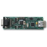
E-blocks™ internet board
Document code: EB023-30-1
2
C compatible bus
page 9
Related parts for EB023
Image
Part Number
Description
Manufacturer
Datasheet
Request
R


Part Number:
Description:
MATRIX CARD FOR HI-LO PROG
Manufacturer:
Cypress Semiconductor Corp
Part Number:
Description:
MATRIX CARD FOR HI-LO PROG
Manufacturer:
Cypress Semiconductor Corp
Datasheet:
Part Number:
Description:
MATRIX CARD FOR HI-LO PROG
Manufacturer:
Cypress Semiconductor Corp
Datasheet:
Part Number:
Description:
MATRIX CARD FOR HI-LO PROG
Manufacturer:
Cypress Semiconductor Corp
Datasheet:
Part Number:
Description:
MATRIX CARD FOR HI-LO PROG
Manufacturer:
Cypress Semiconductor Corp
Part Number:
Description:
MATRIX CARD FOR HI-LO PROG
Manufacturer:
Cypress Semiconductor Corp
Part Number:
Description:
MATRIX CARD FOR HI-LO PROG
Manufacturer:
Cypress Semiconductor Corp
Datasheet:
Part Number:
Description:
MATRIX CARD FOR HI-LO PROG
Manufacturer:
Cypress Semiconductor Corp

Part Number:
Description:
Color Video Chrominance Signal Processing Circuit
Manufacturer:
Matrix Orbital.
Datasheet:
Part Number:
Description:
Recording Video Signal Processing Circuit
Manufacturer:
Matrix Orbital.
Datasheet:
Part Number:
Description:
Driver Circuit
Manufacturer:
Matrix Orbital.
Datasheet: