EM-LPC1700-58 EMBEST, EM-LPC1700-58 Datasheet
EM-LPC1700-58
Specifications of EM-LPC1700-58


Related parts for EM-LPC1700-58


EM-LPC1700-58 Summary of contents
Page 1
... EM-LPC1700 Evaluation Board User Manual V1.2 EMBEST CO., LIMITED Address:Room 509, Luohu Science & Technology Building, #85 Taining Road, Shenzhen, Guangdong, China 518020 Telephone: 0086-755-25621715 or 25635626 ext. 1715 Fax: 0086-755-25616057 E-mail: sales.en@embedinfo.com || support.en@embedinfo.com Website: http://www.embedinfo.com/en www.embedinfo.com/en 1/21 ...
Page 2
... Product List includes .....................................................4 1.2 Getting Start................................................................4 1.3 Jumpers ...................................................................... M-LPC1700 H HAPTER 2.1 Board Overview............................................................6 2.2 Jumpers Setting ...........................................................7 2.3 EM-LPC1700 Block Diagram ...........................................7 2.4 Power Supply ...............................................................8 2.5 Clock Source................................................................8 2.6 Audio ..........................................................................8 2.7 UART ..........................................................................8 2.8 SD Card Interface.........................................................9 2.9 CAN Connector........................................................... 10 2.10 Human-Computer Interface (LCD) ............................. 10 2 ...
Page 3
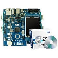
... Chapter 1 Overview EM-LPC1700 is the latest generation of full function evaluation board produced by Embest for NXP ARM Cortex-M3 core-based processors. The comprehensive interfaces, which not only provides a good platform for application development, but also is the first choice for learners. Combining with our company's debugging tools ULINK2, it will offer you a better development environment for saving time and improving efficiency ...
Page 4
... COM interface, Windows XP OS(recommend to install Keil IDE, such as uvision 3) • Connecting COM1 interface of the board to the COM interface using a serial port cable for the information display and input; if you have a JTAG Emulator (optional), you are able to debug and develop the application by connecting to the JTAG interface of the board. ...
Page 5
... Restart a software through P2.9,allows USB devices to Connect POT1 to AD0.2, this operation for analog input make INT0 button available Through the COM0. Make Reset available Through the COM0. Prohibited In-System Programming make P1.28, P1.29, P1.31, P2.2 - P2.6 LEDs available connect P2.9 to UMODE jumper pin 1 ...
Page 6
... Chapter 2 EM-LPC1700 Hardware Specification 2.1 Board Overview Table 2. A List of Hardware Interfaces J1 USART DB9 male connector COM1 J2 USART DB9 male connector COM0 J3 RJ45 network interface J4 Cortex Debug J5 CAN1 DB9 male connector J6 CAN2 DB9 male connector J7 Cortex Debug ETM interface J8 JTAG 20 interface ...
Page 7
... U9 ISP1301 2.2 Jumpers Setting Designation Description JP6 CAN JP8/9 USB JP10 USB JP11 USB/Network 2.3 EM-LPC1700 Block Diagram www.embedinfo.com/en Setting Option Setting Description 1-2 Select CAN Controller 2-3 Select Ethernet Controller Above USB OTG Mode Middle USB HOST Mode Below USB Device Mode ...
Page 8
... Clock Source EM-LPC1700 evaluation board has two clock sources: • 32K Hz crystal as RTC clock source. • crystal as MCU clock source which can be removed when internal RC clock is used as clock source. 2.6 Audio EM-LPC1700 evaluation board has recording and playing functions, the audio file can be played through the external speaker, and the jumper JP6 controls the DAC output and speaker connection ...
Page 9
... UART1 RS232 DB9 connecter signal definition: Pin No UART1_RXD 3 UART1_TXD 4 5 2.8 SD Card Interface STM32 evaluation board has SD card connector and supports SD card read/write operation. SD card and EM-LPC1700 interface connection signal as follows: SD card Pin interface 1 DAT2 2 DAT3 3 CMD 4 VCC 5 CLK 6 VSS 7 DAT0 ...
Page 10
... CAN Connector EM-LPC1700 evaluation board use SN65HVD230 (U10) as CAN driver chip, CAN connecter adopts DB9 to connect wires, here pin2 provides CANL signal and pin7 provides CANH signal. These pins are connected to CAN driver chip SN65HVD230. CAN DB9 connecter pin definition: Pin NO ...
Page 11
... Location of source code: LCD Corresponding chip manual: Datasheet\LCD corresponding\ MR024-9325-51P-B.pdf Steps: Download LCD_Blinky.hex to the FLASH of MCU Testing phenomenon: D2-D9 blink, and LCD displays the LOGO and related words of Embest Co. (3) UART Testing Image file: UART.hex Location of source code: UART Corresponding chip manual: Datasheet\[processor].pdf Steps: 1) Download UART ...
Page 12
... Image file: DAC_Test.hex Location of source code: DAC Corresponding chip manual: Datasheet\[processor].pdf Steps: Download DAC_Test.hex to the FLASH of MCU Testing phenomenon: The buzzer in LCD emits sound signals (6) CAN&ADC Testing Image file: CAN.hex Location of source code: CAN Corresponding chip manual: Documents\Datasheet\Peripherals corresponding\ lpc17xx ...
Page 13
... SD card Testing (RL-ARM holder) Image file: SD_file.hex Location of source code: SD_file Corresponding chip manual: Steps: Download SD_file.hex to the FLASH of MCU, link UART0 to PC through the Cross-serial line, and open the super terminal Testing phenomenon: Hype terminal displays as follows: www.embedinfo.com/en 13/21 ...
Page 14
... Project file include StartUp Code(storage area of startup codes), Source Code (storage area of main source program codes), System Code(program library source files)and Documentation(program document description)folders. 3) Connecting the power line and emulator wire to the board (between ULINK2 and JTAG). www.embedinfo.com/en ...
Page 15
... After download, execute Debug/Start/Stop Debug Session(Ctrl+F5) to debug as follows: or click shortcut con: to start debug. After that, assembly code will show in the main workspace, if you want to see source code, you can right click mouse before Step, choose “Show Source Code for current Address” As follows: ...
Page 16
... You can make use of the debug shortcut icon in the window to execute debug process, the icon as follows: www.embedinfo.com/en 16/21 ...
Page 17
... Appendix A: IO Assignment on EM-LPC1700 Evaluation Board Pin TQFP100 1 TD0/SW0 2 TDI 3 TMS/SWDIO 4 TRST 5 TCK/SWDCLK 6 P0.26 7 P0.25 8 P0.24 9 P0.22 10 VDDA 11 VSSA 12 VREFP RSTOUT 15 VREFN 16 RTCX1 17 RESET 18 RTCX2 19 VBAT 20 P1.31 www.embedinfo.com/en Level Type Input Output JTAG JTAG JTAG JTAG JTAG I/O I/O I/O I/O 3 ...
Page 18
... P1.18 33 P1.19 34 P1.20 35 P1.21 36 P1.22 37 P1.23 38 P1.24 39 P1.25 40 P1.26 41 VSS_1 VDD(REG)(3V3 P1.27 44 P1.28 www.embedinfo.com/en I/O I/O I/O I/O I/O I/O I/O I/O I/O I/O I/O USB XTALIN XTALOUT USB USB I/O I/O 3.3V USB USB GND USB USB Joystick ...
Page 19
... VSS_2 56 P0.22 57 P0.21 58 P0.20 59 P0.19 60 P0.18 61 P0.17 62 P0.15 63 P0.16 64 P2.9 65 P2.8 66 P2.7 67 P2.6 68 P2.5 www.embedinfo.com/en I/O I/O I/O I/O I/O I/O I/O I/O I/O I/O I/O I/O I/O I/O I/O I/O I/O I/O LED CAN CAN USB USB I/O I/O ...
Page 20
... P0.5 81 P0.4 82 P4.28 83 VSS_4 VDD(REG)(3V3 P4.29 86 P1.17 87 P1.16 88 P1.15 89 P1.14 90 P1.10 91 P1.9 92 P1.8 www.embedinfo.com/en I/O I/O 3.3V GND I/O I/O I/O I/O I/O I/O I/O I/O I/O I/O I/O I/O I/O I/O I/O I/O I/O I/O LED LED 3.3V ...
Page 21
... P1.4 94 P1.1 95 P1.0 96 VDD(3V3)_0 97 VSS_5 98 P0.2 99 P0.3 100 RTCK www.embedinfo.com/en I/O I/O I/O JTAG Ethernet Ethernet Ethernet 3.3V GND UART0 UART0 JTAG_RTCK 21/21 ...