EM-LPC1300 EMBEST, EM-LPC1300 Datasheet - Page 6
EM-LPC1300
Manufacturer Part Number
EM-LPC1300
Description
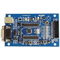
NXP LPC1300 ARM Cortex-M3 Evaluation Board
Manufacturer
EMBEST
Datasheet
1.EM-LPC1300.pdf
(26 pages)
Specifications of EM-LPC1300
Silicon Manufacturer
NXP
Core Architecture
ARM
Core Sub-architecture
Cortex-M3
Features
RS232, USB, JTAG Interface, 12MHz XTAL Frequency
Silicon Core Number
LPC13xx
Silicon Family Name
LPC13xx


1.4 Software resources list
Blinky
GPIO
PMU
SSP
SysTick
Timer32
UART
USB_CDC
USB_HID
USB_HID_rom
USB_Mem
USB_Mem_rom
WDT
I2C_EEPROM
TemperatureSensor
SSP interface
Project Name
Use 16-bits timer to achieve LED1 blinky.
Use GPIO port to achieve input event interrupt. GPIO ports set as input
event,single edge trigger, active high.
Configure PMU to put some of the peripheral in sleep mode.
SSP LOOPBACK mode test.
Configure the SysTick to generate a time base equal to 1 ms. According
systick delay to achieve LED toggle.
Use 32-bits timer to achieve LED1 blinky delay.
Use UART to send and receive data through HyperTerminal.
USB Virtual COM port example.
USB HID (Human Interface Device) demo.
USB HID demo uses functions in rom.
USB Memory Storage demo based on USB Mass Storage Class.
USB Memory Storage demo uses functions in rom.
WatchDog application example.
I2C EEPROM Read/write test
I2C Temperature sensor test
Power Supply: USB powered
Function Description
www.embedinfo.com/en
6/26
Related parts for EM-LPC1300
Image
Part Number
Description
Manufacturer
Datasheet
Request
R

Part Number:
Description:
MIC OMNI .9-10VDC -36DB SENS
Manufacturer:
Knowles Acoustics
Datasheet:
Part Number:
Description:
MIC OMNI .9-10VDC -38.5DB SENS
Manufacturer:
Knowles Acoustics
Datasheet:

Part Number:
Description:
MIC ELECTRET OMNI HIGH SENSITVTY
Manufacturer:
Knowles Acoustics
Datasheet:

Part Number:
Description:
MIC ELECTRET OMNI HISENS W/LEADS
Manufacturer:
Knowles Acoustics
Datasheet:
Part Number:
Description:
Microphone
Manufacturer:
Knowles Acoustics
Datasheet:
Part Number:
Description:
Microphones 3.61 X 3.61 X 2.21MM -68.5 SENS, 12B PORT
Manufacturer:
Knowles Acoustics
Datasheet:
Part Number:
Description:
Microphones 3.61 X 3.61 X 2.21MM -56 SENS, 12B PORT
Manufacturer:
Knowles Acoustics
Datasheet:
Part Number:
Description:
Microphones 3.61 X 3.61 X 2.21MM -56 SENS, 12SL PORT
Manufacturer:
Knowles Acoustics
Datasheet:
Part Number:
Description:
Microphones 3.61 X 3.61 X 2.21MM -58 SENS, 12SL PORT
Manufacturer:
Knowles Acoustics
Datasheet:
Part Number:
Description:
Microphones 3.61 X 3.61 X 2.21MM -52 SENS 12KP PORT
Manufacturer:
Knowles Acoustics
Datasheet:
