FLEX105 EVIDENCE, FLEX105 Datasheet - Page 28

FLEX105
Manufacturer Part Number
FLEX105
Description
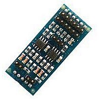
FLEX Multibus RS422 Module
Manufacturer
EVIDENCE
Datasheet
1.FLEX103.pdf
(41 pages)
Specifications of FLEX105
Silicon Manufacturer
Microchip
Application Sub Type
FLEX Multibus RS422 Module
Kit Application Type
Communication & Networking
Kit Contents
Board, CD
Lead Free Status / RoHS Status
Lead free / RoHS Compliant
Slot 1 - JP1 Jumper JP1 is used to control a pin of the module hosted on Slot 1. In
Slot 1 - JP11 Jumper JP11 selects whether the ground reference to the module should
Slot 5 - JP2, JP3, JP4 Jumpers JP2, JP3 and JP4 are used to select if the data, clock
Slot 6 - JP5, JP6, JP7, JP8, JP9, JP10 Jumpers JP5, JP6, JP7 can be used to se-
Slot 7 - JP12, JP13, JP14, JP15 Jumpers JP12, JP13, JP14 and JP15 can be used
Figure 3.18: The figure shows the jumper settings for the SPI chip select of Slot 6.
particular, in position 1-2 a pin of the module is connected to FRCK1 (used for
serial communications with flow control), whereas in position 2-3 it is connected to
the pin RESN (used to handle the input interrupt pin for the TP-UART module).
be given filtered (position 1-2) or not filtered (position 2-3).
and chip select pins of the I2C bus should be connected to the first (position 2-3)
or second (position 1-2) I2C peripheral of the dsPIC. Please note that all the three
jumpers should select the same port (that is, they must be all three in position
1-2 or 2-3).
lectif the data in, data out, and clock of the SPI bus should be connected to the
first (position 2-3) or to the second (1-2) SPI peripheral of the dsPIC (R) DSC.
Please note that all the three jumpers should select the same port (that is, they
must be all three in position 1-2 or 2-3).
Jumpers JP8, JP9, and JP10 control the chip select of the SPI module from either
a general purpose I/O or chip select pin built-in in the microcontroller (see Figure
3.18
to selectif the data in, data out, clock and chip select of the Ethernet bus should
be connected to the first (position 2-3) or to the second (1-2) SPI peripheral of the
dsPIC (R) DSC. Please note that all the four jumpers should select the same port
(that is, they must be all four in position 1-2 or 2-3).
and Table 3.7).
SPI2
SPI1
SS1uP (RB9)
SS2 (RG9)
SSuP (RB8)
SS1 (RB2)
1-2
2-3
1-2
2-3
JP10
JP8
28
1-2
2-3
JP9
SS_JMP


