FLEX105 EVIDENCE, FLEX105 Datasheet - Page 14
FLEX105
Manufacturer Part Number
FLEX105
Description
FLEX Multibus RS422 Module
Manufacturer
EVIDENCE
Datasheet
1.FLEX103.pdf
(41 pages)
Specifications of FLEX105
Silicon Manufacturer
Microchip
Application Sub Type
FLEX Multibus RS422 Module
Kit Application Type
Communication & Networking
Kit Contents
Board, CD
Lead Free Status / RoHS Status
Lead free / RoHS Compliant


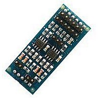
3.1.2 Base board: Light version
The Light FLEX Base Board, depicted in Figure 3.7, has been designed to be as compact
as possible. The Light Versions uses a simplified power supply circuitry, and thus requires
a more careful power supply than the Full Version. Moreover, there is no integrated
USB programming capability. Examples of target applications for the Light FLEX Base
Board are: distributed, battery-powered applications, like sensor networks; small robotic
applications, i.e., for mobile robot control and sensor acquisition.
Figure
power supply connector. Connect the source voltage to the first two pins, named in
figure as V+ and V-.
The power supply of the Light FLEX Base Board varies in the range of 9 - 12V DC.
• JP12: toggle the programming clock line coming from the ICSP programming
• JP13: connects the pull-up resistor to the RX serial line; if unused, the pin is used
• JP15 and JP16: allows to use an external clock oscillator for the dsPIC (R) DSC;
• JP17: allow to toggle the USB shield between GND or PE.
connector between dsPIC (R) DSC and PIC18 micro-controllers;
as a regular GPIO pin;
if disabled, the two pins are used as normal GPIO pins;
3.8
shows a rear view of the Flex Light board. On the top right, there are the
Figure 3.7: FLEX light version.
14
Related parts for FLEX105
Image
Part Number
Description
Manufacturer
Datasheet
Request
R

Part Number:
Description:
FLEX Light Base Board
Manufacturer:
EVIDENCE
Datasheet:

Part Number:
Description:
FLEX MultiBus Daughter Board
Manufacturer:
EVIDENCE
Datasheet:

Part Number:
Description:
FLEX Demo Daughter Board
Manufacturer:
EVIDENCE
Datasheet:

Part Number:
Description:
FLEX Full Base Board
Manufacturer:
EVIDENCE
Datasheet:

Part Number:
Description:
FLEX Blank Thru-Hole Daughter Board
Manufacturer:
EVIDENCE
Datasheet:

Part Number:
Description:
FLEX Multibus Ethernet Module
Manufacturer:
EVIDENCE
Datasheet:

Part Number:
Description:
FLEX Multibus RS232 Module
Manufacturer:
EVIDENCE
Datasheet:

Part Number:
Description:
FLEX Multibus CAN Module
Manufacturer:
EVIDENCE
Datasheet:

Part Number:
Description:
FLEX Multibus SPI Module
Manufacturer:
EVIDENCE
Datasheet:
Part Number:
Description:
FLEX Multibus Serial TTL Module
Manufacturer:
EVIDENCE
Datasheet:

Part Number:
Description:
Microcontroller & Microprocessor Development Tools Demo2 Pack
Manufacturer:
EVIDENCE
Datasheet:

Part Number:
Description:
Microcontroller & Microprocessor Development Tools Mini Kit
Manufacturer:
EVIDENCE
Datasheet:

Part Number:
Description:
Microcontroller & Microprocessor Development Tools Multibus Pack
Manufacturer:
EVIDENCE
Datasheet:

Part Number:
Description:
Microcontroller & Microprocessor Development Tools Demo2 suite
Manufacturer:
EVIDENCE

Part Number:
Description:
Microcontroller & Microprocessor Development Tools Fasttrack suite
Manufacturer:
EVIDENCE
Datasheet: