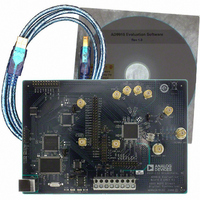
AD9910/PCBZ Analog Devices Inc, AD9910/PCBZ Datasheet - Page 16

AD9910/PCBZ
Manufacturer Part Number
AD9910/PCBZ
Description
Direct Digital Synthesis Evaluation Board
Manufacturer
Analog Devices Inc
Series
AgileRF™r
Specifications of AD9910/PCBZ
Silicon Manufacturer
Analog Devices
Application Sub Type
Direct Digital Synthesizer
Kit Application Type
Clock & Timing
Silicon Core Number
AD9910
Kit Contents
Board
Design Resources
Synchronizing Multiple AD9910 1 GSPS Direct Digital Synthesizers (CN0121)
Main Purpose
Timing, Direct Digital Synthesis (DDS)
Embedded
No
Utilized Ic / Part
AD9910
Primary Attributes
14-Bit DAC, 32-Bit Tuning Word Width
Secondary Attributes
1GHz, Graphical User Interface
Lead Free Status / RoHS Status
Lead free / RoHS Compliant
Lead Free Status / RoHS Status
Lead free / RoHS Compliant, Lead free / RoHS Compliant
Other names
Q3335404
AD9910/PCBZ
REGISTER MAP (SOFTWARE BUFFER) VALUES
To access the Register Map (Software Buffer) Values window,
select Register Map Values from the View drop-down menu (see
Figure 10).
The Register Map (Software Buffer) Values window allows
you to switch between the current values and the values that are
loaded in the software buffer. This window does not allow
changes to the register map. Instead, this window can be used in
conjunction with any other control window to observe register
changes that are written from the software buffer.
The drop-down menu labeled Choose REGMAP Buff allows
you to switch between the Current Values and the New Values.
Under Format, you can chose to view the registers in binary or
hexadecimal format by selecting the applicable option. Note
that when the Auto Refresh check box is selected, the action is
automatically taken without the need to click the Refresh button.
Figure 16. Register Map (Software Buffer) Values window
Rev. 0 | Page 16 of 20
DUT I/O
To access the DUT I/O window, select from the I/O drop-down
menu (see Figure 10).
The DUT I/O window allows you to select the serial I/O port
configuration. Under I/O Port Config, you can select either
2-Wire or 3-Wire mode. Under Data Format, you can select
MSB First or LSB First. See the AD9910 data sheet for more
information on these serial port modes. The Reset I/O Port
effectively resets the I/O port to fix communication errors. This
feature should be used if the part stops responding due to errors
in the data sent to the part. Resetting the part completely has
the same effect, but simply resetting the I/O port is a more
desirable solution.
Figure 17. DUT I/O Window


