APGDT001 Microchip Technology, APGDT001 Datasheet - Page 24
APGDT001
Manufacturer Part Number
APGDT001
Description
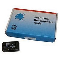
LIN Serial Analyzer
Manufacturer
Microchip Technology
Series
-r
Datasheet
1.APGDT001.pdf
(36 pages)
Specifications of APGDT001
Silicon Manufacturer
Microchip
Application Sub Type
Serial Analyzer
Kit Application Type
Communication & Networking
Features
Used To Send Messages, Monitor Bus Traffic, Perform Errors Checks, Filter Messages
Kit Contents
Board
Tool Type
LIN Serial Analyzer
Lead Free Status / Rohs Status
Lead free / RoHS Compliant
For Use With/related Products
PC to LIN Communications
Available stocks
Company
Part Number
Manufacturer
Quantity
Price
Company:

Part Number:
APGDT001
Manufacturer:
MICROCHIP
Quantity:
12 000


LIN Serial Analyzer User’s Guide Rev2.0
DS51675B-page 20
To save a slave reponse message to a file:
1. See Section 3.4.2 “Save” and Section 3.4.3 “Save As”.
3.5.4.3
This section describes the “Slave Response Frames” field’s two elements.
3.5.4.3.1
The “ID” element displays the identifier byte that is compared to identifier bytes
received from the bus. The ID is entered without the upper two parity bits. Parity is cal-
culated and appended when the message frame is stored in the inernal buffer memory.
The acceptable range of values is 00 to 3F hex (0 to 63 decimal).
3.5.4.3.2
The “Data” portion of the “Slave Response Frames” field displays zero to eight-byte val-
ues, separated by spaces. This are the actual bytes sent over the bus in response to a
recognized ID.
3.5.5
3.5.5.1
Clicking this button stores the selected message content highlighted in the “Slave
Response Frames” field (see the “Save” procedure in Section 3.5.4.2 “Developing
and Storing Response Content”).
3.5.5.2
Click the Add button to add a new message to the “Slave Response” field
3.5.5.3
Allows the selected message in the “Slave Response Frames” field to be edited.
3.5.5.4
Clicking the Delete button deletes the content that is highlighted in the “Master Frames”
field. (see the “Delete” procedure in Section 3.5.4.2 “Developing and Storing
Response Content”).
3.5.5.5
Clicking this button clears the both the contents of the “Slave Response Frames” win-
dow and the internal buffer memory. The buffer status is updated to show no used bytes
and bytes remaining.
3.5.6
The checksum value is computed at send time. Selecting one of the
option buttons in the “Checksum” group, shown at right, determines
the type of checksum that will be calculated for all transmitted
master message frames, highlighted in the “Master Frames” field.
• classic – The checksum includes all data bytes.
• enhanced – The checksum includes identifier byte and all data
• forced – (Enabled only in Debug mode.) The last byte in the message string is
bytes.
sent in place of the calculated checksum. This is useful in checking master error
handling.
SLAVE RESPONSE FRAMES FIELD ELEMENTS
Slave Response Message Controls
SAVE BUTTON
ADD BUTTON
EDIT BUTTON
DELETE BUTTON
CLEAR ALL BUTTON
Checksum Group
ID
DATA
© 2008 Microchip Technology Inc.
Related parts for APGDT001
Image
Part Number
Description
Manufacturer
Datasheet
Request
R

Part Number:
Description:
Manufacturer:
Microchip Technology Inc.
Datasheet:
Part Number:
Description:
Manufacturer:
Microchip Technology Inc.
Datasheet:
Part Number:
Description:
Manufacturer:
Microchip Technology Inc.
Datasheet:
Part Number:
Description:
Manufacturer:
Microchip Technology Inc.
Datasheet:
Part Number:
Description:
Manufacturer:
Microchip Technology Inc.
Datasheet:
Part Number:
Description:
Manufacturer:
Microchip Technology Inc.
Datasheet:
Part Number:
Description:
Manufacturer:
Microchip Technology Inc.
Datasheet:
Part Number:
Description:
Manufacturer:
Microchip Technology Inc.
Datasheet: