APGDT001 Microchip Technology, APGDT001 Datasheet - Page 17
APGDT001
Manufacturer Part Number
APGDT001
Description
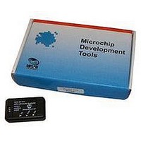
LIN Serial Analyzer
Manufacturer
Microchip Technology
Series
-r
Datasheet
1.APGDT001.pdf
(36 pages)
Specifications of APGDT001
Silicon Manufacturer
Microchip
Application Sub Type
Serial Analyzer
Kit Application Type
Communication & Networking
Features
Used To Send Messages, Monitor Bus Traffic, Perform Errors Checks, Filter Messages
Kit Contents
Board
Tool Type
LIN Serial Analyzer
Lead Free Status / Rohs Status
Lead free / RoHS Compliant
For Use With/related Products
PC to LIN Communications
Available stocks
Company
Part Number
Manufacturer
Quantity
Price
Company:

Part Number:
APGDT001
Manufacturer:
MICROCHIP
Quantity:
12 000


© 2008 Microchip Technology Inc.
3.3.7
This field displays any of the error types described in this section. If multiple errors are
detected, only one is displayed.
3.3.7.1
The parity is calculated on the frame identifier bits as shown in Equation 3-1.
EQUATION 3-1:
3.3.7.2
A slave or master node that is transmitting a bit on the bus also monitors the bus. A TX
bit error is when the bit or byte value that is received is different from the bit or byte
value that is transmitted.
3.3.7.3
A checksum error is when the inverted modulo-256 sum over all received data bytes
and the protected identifier (when using enhanced checksum) and the received
checksum byte field does not result in $FF.
3.3.7.4
A byte field framing error is when the ninth bit after a valid Start bit is dominant. This
check does not apply to the Break character.
3.3.7.5
This value displays when a new Break/Sync/ID header was detected, but no data was
received within the bus time-out period.
3.3.7.6
This displays when data characters were received before a valid Sync Break header
was detected.
3.3.7.7
This value indicates that the time interval allocated for an eight-byte message expired.
This time is set to approximately 140% of a single bit time.
The time-out may also be configured to a fixed value not dependent on baud rate.
3.3.7.8
This value displays when a valid Sync Break is not detected by the UART. A Break was
“assumed” because the first byte received was 0x00, but without a framing error.
P0 = ID0 ℘? ID1 ℘? ID2 ℘?
P1 = - (ID1 ℘? ID3 ℘? ID4 ℘? I
† P0 is bit 6 and P1 is bit 7 of the ID byte.
Note:
Note:
Note:
Note:
Errors
PARITY
TX BIT
CHECKSUM
FRAMING
NO ANSWER
BREAK
BUS TIME-OUT
SWBREAK
This function is not currently implemented.
This function is not currently implemented.
This function is not currently implemented.
This function is not currently implemented.
PARITY CALCULATIONS
LIN Serial Analyser PC Program
†
DS51675B-page 13
Related parts for APGDT001
Image
Part Number
Description
Manufacturer
Datasheet
Request
R

Part Number:
Description:
Manufacturer:
Microchip Technology Inc.
Datasheet:
Part Number:
Description:
Manufacturer:
Microchip Technology Inc.
Datasheet:
Part Number:
Description:
Manufacturer:
Microchip Technology Inc.
Datasheet:
Part Number:
Description:
Manufacturer:
Microchip Technology Inc.
Datasheet:
Part Number:
Description:
Manufacturer:
Microchip Technology Inc.
Datasheet:
Part Number:
Description:
Manufacturer:
Microchip Technology Inc.
Datasheet:
Part Number:
Description:
Manufacturer:
Microchip Technology Inc.
Datasheet:
Part Number:
Description:
Manufacturer:
Microchip Technology Inc.
Datasheet: