EVK-SH3000USB Semtech, EVK-SH3000USB Datasheet - Page 13
EVK-SH3000USB
Manufacturer Part Number
EVK-SH3000USB
Description
Tools, Development Kit
Manufacturer
Semtech
Datasheet
1.EVK-SH3000USB.pdf
(19 pages)
Specifications of EVK-SH3000USB
Kit Contents
Evaluation Kit
Tool / Board Applications
MicroBuddy Devices
Development Tool Type
Hardware / Software - Eval/Demo Board
Mcu Supported Families
SH3000
For Use With
SH3000 MicroBuddy
Lead Free Status / RoHS Status
na


SH3000 Evaluation Kit User Guide v0.96
SYSTEM MANAGEMENT
E. FLL Block, FLL Divide ratio – Target frequency for the HF oscillator. Once enabled the FLL adjusts the
F. This is a diagrammatic representation of the LF-block-generated internal 32.768 kHz reference frequency, used
G. Simulate MCU Clock Stop – This button tells the Cypress MCU on the evaluation board to stop output of
H. Autoset block, frequency assist – This value can be used by the user to select a target frequency for
I.
J. Apply – Updates the register table only with the settings set on this page. By pressing the Registers tab, the
K. Change Now – Updates the register table with the settings set in this window, and updates the MicroBuddy
L. Frequency – Resultant frequency output from the MicroBuddy’s CLK
M. HF Clock output block, 32.768 kHz – This button allows the system to force the MicroBuddy’s CLK
N. HF Clock output block, Enabled – This button allows the system to manually enable or disable the
O. FLL Post Scaler block, value – Value of the post scale divider block, which divides the internal HF
P. FLL Post Scaler block, setting – This setting adjusts the amount of division applied to the HF clock
Q. DCO block, DCO value – Current value of the DCO (Digitally controlled oscillator). When the FLL is not
R. DCO block, Force DCO on – Forces the DCO to turn on immediately after power up.
S. Spread Spectrum block, Spread Spectrum enable – Enables the spread spectrum circuit to reduce
T. Spread Spectrum block, Spread Spectrum value – This value is the amount of spread spectrum noise
U. HF Clock – The tab that displays this window.
DCO block to match this value. This frequency is determined by the equation Frequency = (FLL_Divide_ratio+1)
x (LFO_value / 16), which generally would be f = (FLL_Divide_Ratio +1) x 2048
as a reference for the HF clock.
clock cycles to the CLK
demonstrates the host MCU HALT or STOP functions.
CLK
options and settings to quickly set up a desired frequency and to see what settings would result in the closest
match. This value represents kHz, and can vary from 32.768 kHz to 4 MHz.
Autoset block, Help me set values – This button is used with the frequency assist value (G) in order to
help users confused with the number of controls to easily set their desired frequency.
user can see which registers this block affects.
immediately with these values.
pin to 32.768 kHz. This can be used if the user wants to change the HF clock settings, but the system CPU
cannot withstand the clock variations that occur when Coarse Lock (C) is enabled.
CLK
frequency into the clock frequency that is output on the CLK
signal (N).
enabled, this is the source of the HF signal, its range is from 0x00000 to 0x1FFFF [again, this represents a
frequency derived by DCO Value x 2048]. This value is written into nonvolatile memory at the factory to provide
an “instant on” frequency of 2 MHz at initial power-up. This value can be changed, but is only useful if the FLL is
disabled. The frequency derived from this block alone is in open-loop mode with no feedback and a consequently
large tolerance in absolute accuracy. The FLL changes this value to achieve the target value in its block, and
also locks this value to the accuracy of the internal 32.768 kHz oscillator.
EMI. Please refer to the SH3000 Reference Manual for more details.
added to the HF frequency. The higher this value is set, the lower the EMI emission, but the greater the jitter on
the clock frequency. The values labeled here represent the amount of frequency change to be applied to the HF
clock, which is then divided down by the FLL Post Scaler .
OUT
OUT
. This value along with the set button (H) allows the user who may be confused by a large array of
pin of the MicroBuddy.
IN
pin on the MicroBuddy. This causes the MicroBuddy to enter standby mode. This
2003-03
13
OUT
pin of the MicroBuddy.
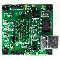
EVK-SH3000USB MicroBuddy™
OUT
pin.
Copyright ©2002-2003 Semtech Corporation
Evaluation Kit User Guide
www.semtech.co
Preliminary
OUT
m
Related parts for EVK-SH3000USB
Image
Part Number
Description
Manufacturer
Datasheet
Request
R

Part Number:
Description:
EVALUATION BOARD
Manufacturer:
Semtech
Datasheet:
Part Number:
Description:
EVALUATION BOARD
Manufacturer:
Semtech
Datasheet:
Part Number:
Description:
VOLTAGE SUPPRESSOR, TRANSIENT SEMTECH
Manufacturer:
Semtech
Datasheet:

Part Number:
Description:
HIGH VOLTAGE CAPACITORS MONOLITHIC CERAMIC TYPE
Manufacturer:
Semtech Corporation
Datasheet:
Part Number:
Description:
EZ1084CM5.0 AMP POSITIVE VOLTAGE REGULATOR
Manufacturer:
Semtech Corporation
Datasheet:
Part Number:
Description:
3.0 AMP LOW DROPOUT POSITIVE VOLTAGE REGULATORS
Manufacturer:
Semtech Corporation
Datasheet:
Part Number:
Description:
Manufacturer:
Semtech Corporation
Datasheet:
Part Number:
Description:
RailClamp Low Capacitance TVS Diode Array
Manufacturer:
Semtech Corporation
Datasheet:
Part Number:
Description:
Manufacturer:
Semtech Corporation
Datasheet:
Part Number:
Description:
Manufacturer:
Semtech Corporation
Datasheet:
Part Number:
Description:
Manufacturer:
Semtech Corporation
Datasheet:
Part Number:
Description:
Manufacturer:
Semtech Corporation
Datasheet: