N5181A-506 AGILENT TECHNOLOGIES, N5181A-506 Datasheet - Page 17
N5181A-506
Manufacturer Part Number
N5181A-506
Description
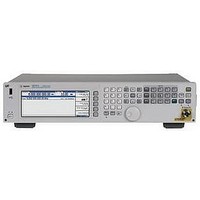
SIGNAL GENERATOR, FREQUENCY/PULSE, 6GHZ
Manufacturer
AGILENT TECHNOLOGIES
Series
N5181Nr
Datasheet
1.N5181AK-1EA.pdf
(22 pages)
Specifications of N5181A-506
Signal Generator Type
Sweep Function
Bandwidth
6GHz
External Height
103mm
External Width
426mm
External Depth
432mm
Kit Contents
2RU
Analyzer Functions
Frequency
Lead Free Status / RoHS Status
na


Recommended
calibration cycle
ISO compliant
Front panel connectors
Rear panel connectors
1.
2.
RF output
USB 2.0
RF output
(Option 1EM or N5161A)
Sweep out
AM
FM
Pulse
Trigger in
Trigger out
Reference input
10 MHz out
USB 2.0
All connectors are BNC unless otherwise noted.
All N5161A MXG ATE connectors located on rear panel.
2
1
1
Accepts TTL and CMOS level signals for triggering
point-to-point in sweep mode. Damage levels are ≤ –0.3 V
and ≥ +5.3 V.
Outputs a TTL and CMOS compatible level signal for use
with sweep mode. The signal is high at start of dwell, or
when waiting for point trigger in manual sweep mode; low
when dwell is over or point trigger is received. This output
can also be programmed to indicate when the source is
settled, pulse synchronization, or pulse video. Nominal
output impedance 50 ohms. Input damage levels are
≤ –0.3 V and ≥ +5.3 V.
Accepts a 10 MHz reference signal used to frequency lock
the internal timebase. Option 1ER adds the capability to
lock to a frequency from 1 MHz to 50 MHz. Nominal input
level –3.5 to +20 dBm, impedance 50 Ω, sine or square
waveform.
Outputs the 10 MHz reference signal used by internal
timebase. Level nominally +3.9 dBm. Nominal output
impedance 50 Ω. Input damage level is +16 dBm.
The USB connector provides remote programming
functions via SCPI.
36 months. Agilent is committed to providing you with
the lowest total cost to own and operate equipment. In
support of this commitment, Agilent has verified that the
stability of this product's architecture justifies a longer
calibration interval of 3 years.
The Agilent N5181A MXG is manufactured in an ISO-9001
registered facility in concurrence with Agilent Technologies’
commitment to quality.
Outputs the RF signal via a precision N type female connector.
Used with a memory stick for transferring instrument
states, licenses and other files into or out of the
instrument. Also used with U2000 Series USB average
power sensors. For a current list of supported memory
sticks, visit www.agilent.com/find/MXG, click on
Technical Support, and refer to FAQs: Waveform
Downloads and Storage.
Outputs the RF signal via a precision N type female connector.
Generates output voltage, 0 to +10 V when the signal
generator is sweeping. This output can also be programmed
to indicate when the source is settled or output pulse
video and is TTL and CMOS compatible in this mode.
Output impedance < 1 Ω, can drive 2 kΩ. Damage levels
are ±15 V.
External AM input. Nominal input impedance is 50 Ω.
Damage levels are ± 5 V.
External FM input. Nominal input impedance is 50 Ω.
Damage levels are ± 5 V.
External pulse modulation input. This input is TTL and
CMOS compatible. Low logic levels are 0 V and high logic
levels are +1 V. Nominal input impedance is 50 Ω. Input
damage levels are ≤ –0.3 V and ≥ +5.3 V.
17