72-7985 TENMA, 72-7985 Datasheet - Page 6
72-7985
Manufacturer Part Number
72-7985
Description
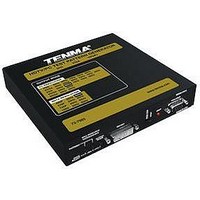
SIGNAL GENERATOR, HDTV PATTERN
Manufacturer
TENMA
Datasheet
1.72-7985.pdf
(11 pages)
Specifications of 72-7985
Signal Generator Type
HDTV Pattern


© Copyright 2005, Tenma Test Equipment. All rights reserved.
405 S. Pioneer Blvd. Springboro Ohio 45066
1.
2.
Plug the supplied AC adapter to the POWER input connector located on
the rear of the unit. To avoid risk of possible damage, use the supplied
adapter only. The green LED indicator will light, indicating the unit is
powered.
Included in the package are all necessary cables: DVI cable, VGA cable,
and HD15 to component Cable (shown below). For testing HDMI
connections, an optional cable (MCM #24-9316) may be purchased
separately.
The front panel of the unit is pictured below:
The two output connectors, DVI OUT and VGA/YPbPr, are
simultaneously active when the unit is on.
The VGA output serves two purposes: ▪Standard RGBHV VESA signals,
similar to that of most personal computers ▪YPbPr output, similar to the
Red/Blue/Green component video High Definition Television (HTVD)
signals. The output mode is determined by the slide switch immediately
left of this connector.
The red LED indicator, next to the slide switch, illuminates when the
output is one of the standard HDTV resolutions AND the slide switch is in
YPbPr mode.
2. Installation
3. Operation