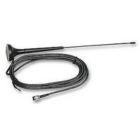
GSM20-ANT RF Solutions, GSM20-ANT Datasheet - Page 9

GSM20-ANT
Manufacturer Part Number
GSM20-ANT
Description
ANTENNA, MAESTRO 20
Manufacturer
RF Solutions
Datasheet
1.GSM20-DINRL.pdf
(15 pages)
Specifications of GSM20-ANT
Svhc
No SVHC (15-Dec-2010)
Lead Free Status / RoHS Status
Lead free / RoHS Compliant
GSM & GPRS Modem
8
2.4 Connect the modem to external device
You can use the optional ‘Y’ cable to connect the modem’s Sub-D connector to external
controller/computer. Note : The modem CANNOT be connected to the ‘Line’ jack of a landline telephone
directly.
Connection example using optional ‘Y’ cable:
4p4c
Handset of phone
Maestro
Sub-D 15 pin
DB-9
100
RS-232 port of PC
2.5 Connecting the DC power supply
Connect the open ending of the included power cord to a DC supply. Refer to the following for power
supply requirement.
Input voltage range
5V – 32V
Rated current
650 mA
AC-DC Adaptor
or battery
Solder wire
Connect the connector to the modem. The modem will turn on automatically.
The status indicator on the modem will be lit when power on. After a few seconds it will go flashing slowly
(registered to the network successfully, refer section 1.2.1).
TM
Chapter 3 describes how to communicate with the modem in Microsoft Windows
environment.
©2007 REG No 277 4001, ENGLAND.
Page 8
DS100-1 May ’07
www.rfsolutions.co.uk


