TS-01-30-1000 IGUS, TS-01-30-1000 Datasheet - Page 7
TS-01-30-1000
Manufacturer Part Number
TS-01-30-1000
Description
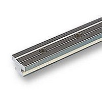
LINEAR RAIL
Manufacturer
IGUS
Series
DryLin Tr
Datasheet
1.TS-01-30-1000.pdf
(12 pages)
Specifications of TS-01-30-1000
Width
15mm
Body Material
Aluminium
External Length / Height
300mm
Lead Free Status / RoHS Status
na


61.12
Lifetime calculation, CAD files and much more support
DryLin
For the exact calculation of the DryLin
Guide System it is essential to find out whether the
position of the forces is
within the allowable limits, and if the gliding element
where the highest forces occur is not overloaded.
The calculation of the necessary driving force and
the maximum speed allowed is important. Each
mounting version requires a different formula for
calculation. Factors concerning shocks and acce-
leration forces are not included in the calculation,
therefore the maximum load and allowable load
must be monitored.
Variables in the calculations:
Fa
Fs
Fy, Fz
sx, sy, sz : Distance of the mass force
ay, az
wx
LX
Zm
Y0
b
μ
ZW
The constant values:
Part No.
TW-01-15
TW-01-20
TW-01-25
TW-01-30
: Drive Force
: Applied Mass
: Bearing Load
: Distance of the mass force
: Distance between carriages
: Constant from table below
: Constant from table below
: Constant from table below
: Distance between
: Coefficient of friction,
: Number of carriages per rail
in y- or z-direction
in x-, y- or z-direction
in y- or z-direction
on a rail
guide rails
μ = 0 for static loads,
μ = 0.2 for dynamic loads
®
T – System Design
[mm]
L
29
35
41
49
X
[mm]
Z
16
23
25
29
M
®
T Linear
[mm]
11,5
15,0
19,0
21,5
[mm]
[mm]
[mm]
[mm]
[mm]
[mm]
[mm]
[mm]
Y
0
[N]
[N]
[N]
www.igus.de/en/DryLinT
Recommended procedure:
Select the mounting version
z
z
z
Check to see whether the offset distances of the
applied forces are within the permissible values
Calculate the necessary drive force
Calculate the maximum bearing load in y- and z-
directions
Check calculated load for both y and z with the
table on page 37.11 - Maximum permissible load
for Fymax & Fzmax
Check calculated mean speed for the load from
step 5 with the graph on page 37.11
Coefficients:
K
K
K
K
K
K
K
1
2
3
4
5
6
7
horizontal
1 rail and 1 carriage
1 rail and 2 carriages
2 rails and 4 carriages
lateral
1 rail and 1 carriage
1 rail and 2 carriages
2 rails and 4 carriages
vertical
1 rail and 1 carriage
1 rail and 2 carriages
2 rails and 4 carriages
Pages 61.14 to 61.16
Page 61.14 to 61.16
Page 61.14 to 61.16
Page 61.13, table 61.2
Page 61.13, Graph. 61.4
|(sy+Y
|(ay+Y
(sy+Y
1 carriage
|sz / Z
|az / L
|sx / L
sz / L
1 rail,
0
0
0
)/ Z
)/ L
)/ L
m
x
x
x
|
|
|
m
x
x
2nd step:
3nd step:
4nd step:
5nd step:
6nd step:
1st step:
| |(ay+Y
| |(sy+Y
(sy+Y
2 carriages 3–4 carriages
|az / W
|sx / W
|sz / W
|sz / Z
1 rail,
0
0
0
)/ W
)/ W
)/ Z
m
x
x
x
|
|
|
|
m
x
x
| |(ay+Y
| |(sy+Y
(sy+Y
|(sz / b)-0,5|
Page 61.14
Page 61.14
Page 61.14
Page 61.15
Page 61.15
Page 61.15
Page 61.16
Page 61.16
Page 61.16
|az / W
|sx / W
|sz / W
2 rails,
0
0
0
)/ W
)/ W
)/ b|
x
x
x
|
|
|
x
x
|
Related parts for TS-01-30-1000
Image
Part Number
Description
Manufacturer
Datasheet
Request
R

Part Number:
Description:
CONN HEADER .100" 1POS TIN PCB
Manufacturer:
Samtec Inc
Datasheet:
Part Number:
Description:
CONN HEADER .100" 1POS GOLD PCB
Manufacturer:
Samtec Inc
Datasheet:

Part Number:
Description:
LINEAR CARRIAGE
Manufacturer:
IGUS
Datasheet:

Part Number:
Description:
BRACKET SET
Manufacturer:
IGUS
Datasheet:
Part Number:
Description:
BRACKET SET
Manufacturer:
IGUS
Datasheet:


Part Number:
Description:
TOUCH PANEL FOR 320X240 LCD
Manufacturer:
Newhaven Display
Datasheet:
Part Number:
Description:
TOUCH PANEL 140X1.4.0 TFT
Manufacturer:
Newhaven Display
Datasheet:
Part Number:
Description:
TCH PANEL 140X104 RESISTIVE MONO
Manufacturer:
Newhaven Display
Datasheet:
