TW-01-15 IGUS, TW-01-15 Datasheet
TW-01-15
Specifications of TW-01-15


Related parts for TW-01-15


TW-01-15 Summary of contents
Page 1
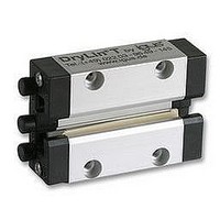
DryLin ® T Linear Guide System – Maintenance-Free, Adjustable and Quiet Corrosion resistant Wear resistant Low coefficient of friction Extremely quiet operation No lubrication necessary mm 61.1 ...
Page 2
... All steel parts are galvanized or of stainless steel The end plate is solid plastic Aluminium, extruded section 0,5 Hard anodized aluminium, 50 μm 500 HV Aluminium, extruded section 0,5 Anodized aluminium Maintenance-free plain bearing iglidur Stainless steel, galvanized steel Plastic 15 m/s -40 °C to +90 °C www.igus.de/en/DryLinT ® J ...
Page 3
... T – Permissible dynamic load Lifetime calculation, CAD files and much more support DryLin ® demanding use in the packaging industry [Nm] [Nm] 1,8 1 4,4 4 100 100 Graph 3.3: Designation of load directions 1 www.igus.de/en/DryLinT 0(- TK-01-15 TK-01-20 TK-01-25 TK-01-30 TK-04-15 TK-04-12 TK-04-09 y-direction z-direction 10 mm 61.3 ...
Page 4
... The Polymer sliding elements of iglidur ® J are fixed by the metal end caps and cannot be lost. This system is compatible with many standard ball bearing systems and is available in the following sizes: TW-01-20, TW-01-25, and TW-01-30. DryLin ® The clearance of DryLin sliding elements are mounted with positive locking (form-fitted) into the chromated zinc slide carriages ...
Page 5
... Please contact our technical experts if you have any questions on the engineering design and/or installation. Floating bearings for linear slide guides In the case of a system with two parallel guides, one side needs to be configured with floating bearings. A suitable solution comprising fixed & floating bearings is available for every installation position, whether horizontal, vertical or lateral ...
Page 6
... Press hard against the readjusting spring. You must have already loosened the respective adjustment screws. Use the correct size pin for this purpose: 2.5 mm for TW-01-20 and TW-01-15 3.0 mm for TW-01-25 3.0 mm for TW-01-30 Adjusting the clearance: DryLin The DryLin ® ...
Page 7
... Distance between guide rails [mm] μ : Coefficient of friction, μ for static loads, μ = 0.2 for dynamic loads ZW : Number of carriages per rail The constant values: Part No [mm] [mm] [mm] TW-01- 11,5 TW-01- 15,0 TW-01- 19,0 TW-01- 21,5 Recommended procedure: 1st step: Select the mounting version ...
Page 8
... Graph 61.4: Diagram for determining the maximum permissible speed for the calculated bearing load Part No max, max [N] TW-01-15 2000 TW-01-20 3700 TW-01-25 5000 TW-01-30 7000 Table 61.2: Maximum permissible load Lifetime calculation, CAD files and much more support 50 100 200 Bearing load (centre) [N] www.igus.de/en/DryLinT TW-01-30 TW-01-25 TW-01-20 TW-01-15 500 1000 2000 mm 61.13 ...
Page 9
... Variation: 1 rail, 1 carriage < < < < Koordinaten- sz ursprung y Maximum permissible distances between applied forces: Variation: 1 rail, 2 carriages Variation: 2 rails, 4 carriages < < Zero point Fixed bearing 2nd step: Check to see whether the maximum distances of 0 the applied forces are within the permissible values. ...
Page 10
... T – Mounting Version Lateral 2nd step: Check to see whether the maximum distances of the applied forces are within the permissible values. (See maximum permissible distances) 3nd step: Calculate the necessary drive force First two calculations must be made: ( μ · 1– 2μ K ...
Page 11
... T – Mountig Version – Vertical Maximum permissible distances between applied forces: Variation: 1 rail, 1 carriage < < < < Zero point Maximum permissible offset distances between applied forces: Variation: 1 rail, 2 carriages Variation: 2 rails, 4 carriages < < Floating bearing ay Fa Zero point 2nd step: Check to see whether the maximum distances of the applied forces are within the permissible values ...
Page 12
... Order example: TS-01-15, 2000 for a guide rail TS-01- length For rails without mounting holes, please use bearing suffix “without mounting hole” DryLin ® T Guide Carriages Part No. Weight H ± 0,35 [kg] [mm] [mm] [mm] [mm] [mm] [mm] [mm] [mm] [mm] [mm] TW-01-15 0,11 24 TW-01-20 0,19 30 TW-01-25 0,29 36 TW-01-30 0,50 ...