VLMW33U2AA-5K8L-18 Vishay, VLMW33U2AA-5K8L-18 Datasheet
VLMW33U2AA-5K8L-18
Specifications of VLMW33U2AA-5K8L-18


Related parts for VLMW33U2AA-5K8L-18


VLMW33U2AA-5K8L-18 Summary of contents
Page 1
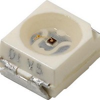
... Angle of half intensity: ± 60° PARTS TABLE PART VLMW33S2V1-5K8L-08 VLMW33S2V1-5K8L-18 VLMW33T2U2-5K8L-08 VLMW33T2U2-5K8L-18 VLMW33U2AA-5K8L-08 VLMW33U2AA-5K8L-18 VLMW33T2AA-5K8L-08 VLMW33T2AA-5K8L-18 ** Please see document “Vishay Material Category Policy”: Document Number 81273 Rev. 1.6, 22-Feb-11 Power SMD LED PLCC-2 FEATURES • High efficient InGaN technology • ...
Page 2
... T I amb 10 µ FSM amb Mounted on PC board R 2 thJA (pad size > VLMW33.., WHITE PART VLMW33S2V1 VLMW33T2U2 VLMW33U2AA VLMW33T2AA VLMW33 VLMW33 µ order to ensure availability, single brightness groups will not be orderable similar manner for colors where wavelength groups are measured and binned, single wavelength groups will be shipped on MAX ...
Page 3
... Figure 2. Rel. Luminous Intensity vs. Angular Displacement For technical support, please contact: LED@vishay.com VLMW33.. Vishay Semiconductors X 0.330 0.330 7L 0.347 0.345 0.330 0.330 7K 0.338 0.352 0.345 0.347 8L 0.367 0.364 0.352 ...
Page 4
... VLMW33.. Vishay Semiconductors 100 400 450 500 550 600 650 700 750 λ - Wavelength (nm) 16196 Figure 3. Relative Intensity vs. Wavelength 100 2 Forward Voltage (V) 19035 F Figure 4. Forward Current vs. Forward Voltage 10 1 0.1 0. Forward Current (mA) 16194 F Figure 5. Relative Luminous Intensity vs. Forward Current www ...
Page 5
... Drawing-No.: 6.541-5067.01-4 Issue: 5; 04.11.08 20541 Document Number 81273 Rev. 1.6, 22-Feb- 0.35 0.37 A 1.6 (1.9) For technical support, please contact: LED@vishay.com VLMW33.. Vishay Semiconductors technical drawings according to DIN specifications Mounting Pad Layout 1.2 area covered with solder resist 4 www.vishay.com 5 ...
Page 6
... Vishay Semiconductors METHOD OF TAPING/POLARITY AND TAPE AND REEL SMD LED (VLM.3 - SERIES) Vishay’s LEDs in SMD packages are available in an antistatic 8 mm blister tape (in accordance with DIN IEC 40 (CO) 564) for automatic component insertion. The blister tape is a plastic strip with impressed component cavities, covered by a top tape ...
Page 7
... Time (s) 19885 Figure 13. Vishay Lead (Pb)-free Reflow Soldering Profile (acc. to J-STD-020) TTW Soldering (acc. to CECC00802) 300 5 s lead temperature 250 235 °C second full line: typical wave to 260 °C ...
Page 8
... VISHAY SEMICONDUCTORS STANDARD BAR CODE LABELS The Vishay Semiconductors standard bar code labels are printed at final packing areas. The labels are on each packing unit and contain Vishay Semiconductors specific data. For technical support, please contact: LED@vishay.com CAUTION ...
Page 9
... Vishay product could result in personal injury or death. Customers using or selling Vishay products not expressly indicated for use in such applications their own risk and agree to fully indemnify and hold Vishay and its distributors harmless from and against any and all claims, liabilities, expenses and damages arising or resulting in connection with such use or sale, including attorneys fees, even if such claim alleges that Vishay or its distributor was negligent regarding the design or manufacture of the part ...