VLMW33U2AA-5K8L-08 Vishay, VLMW33U2AA-5K8L-08 Datasheet
VLMW33U2AA-5K8L-08
Specifications of VLMW33U2AA-5K8L-08
Available stocks


Related parts for VLMW33U2AA-5K8L-08


VLMW33U2AA-5K8L-08 Summary of contents
Page 1
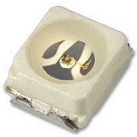
... Package: SMD PLCC-2 • Product series: power • Angle of half intensity: ± 60° PARTS TABLE PART VLMW33S2V1-5K8L-08 VLMW33S2V1-5K8L-18 VLMW33T2U2-5K8L-08 VLMW33T2U2-5K8L-18 VLMW33U2AA-5K8L-08 VLMW33U2AA-5K8L-18 VLMW33T2AA-5K8L-08 VLMW33T2AA-5K8L-18 Document Number 81273 Rev. 1.5, 25-Oct-07 Power SMD LED PLCC-2 FEATURES • High efficient InGaN technology • ...
Page 2
... F ≤ 10 µ FSM stg T amb mounted on PC board R 2 thJA (pad size > VLMW33.., WHITE PART VLMW33S2V1 VLMW33T2U2 VLMW33U2AA VLMW33T2AA VLMW33 VLMW33 µ order to ensure availability, single brightness groups will not be orderable similar manner for colors where wavelength groups are measured and binned, single wavelength groups will be shipped on MAX any one reel ...
Page 3
... Figure 2. Rel. Luminous Intensity vs. Angular Displacement VLMW33.. Vishay Semiconductors X Y 0.330 0.330 0.330 0.347 0.347 0.371 0.345 0.352 0.330 0.310 0.330 0.330 0.338 0.342 0.352 0.344 0.345 ...
Page 4
... VLMW33.. Vishay Semiconductors 100 400 450 500 550 600 650 700 750 800 λ - Wavelength (nm) 16196 Figure 3. Relative Intensity vs. Wavelength 100 10 1 2.0 2.5 3.0 3.5 4 Forward Voltage (V) 19035 F Figure 4. Forward Current vs. Forward Voltage 10 1 0.1 0. Forward Current (mA) 16194 F Figure 5. Relative Luminous Intensity vs. Forward Current www ...
Page 5
... X-par 19784_3 Figure 9. Coordinates of Colorgroups PACKAGE DIMENSIONS in millimeters 20541 Document Number 81273 Rev. 1.5, 25-Oct- Mounting Pad Layout 1.6 (1.9) VLMW33.. Vishay Semiconductors 1.2 area covered with solder resist 4 www.vishay.com 5 ...
Page 6
... Vishay Semiconductors METHOD OF TAPING/POLARITY AND TAPE AND REEL SMD LED (VLM.3 - SERIES) Vishay’s LEDs in SMD packages are available in an antistatic 8 mm blister tape (in accordance with DIN IEC 40 (CO) 564) for automatic component insertion. The blister tape is a plastic strip with impressed component cavities, covered by a top tape ...
Page 7
... Time (s) 19885 Figure 13. Vishay Lead (Pb)-free Reflow Soldering Profile (acc. to J-STD-020C) TTW Soldering (acc. to CECC00802) 300 5 s 250 second 235 °C...260 °C wave first wave dotted line: process limits 200 ca ...
Page 8
... Electro-static sensitive devices warning labels are on the packaging. VISHAY SEMICONDUCTORS STANDARD BAR CODE LABELS The Vishay Semiconductors standard bar code labels are printed at final packing areas. The labels are on each packing unit and contain Vishay Semiconductors specific data CAUTION 2a This bag contains MOISTURE – ...
Page 9
... Various national and international initiatives are pressing for an earlier ban on these substances. Vishay Semiconductor GmbH has been able to use its policy of continuous improvements to eliminate the use of ODSs listed in the following documents. 1. Annex A, B and list of transitional substances of the Montreal Protocol and the London Amendments respectively 2 ...
Page 10
... Vishay disclaims any and all liability arising out of the use or application of any product described herein or of any information provided herein to the maximum extent permitted by law. The product specifications do not expand or otherwise modify Vishay’ ...