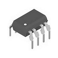
IL300-F-X006 Vishay, IL300-F-X006 Datasheet - Page 7

IL300-F-X006
Manufacturer Part Number
IL300-F-X006
Description
Optocoupler
Manufacturer
Vishay
Datasheet
1.IL300-F-X006.pdf
(11 pages)
Specifications of IL300-F-X006
Leaded Process Compatible
Yes
Current Transfer Ratio
0.5 % to 1.1 %
Forward Current
10 mA
Isolation Voltage
5300 Vrms
Maximum Fall Time
1.75 us
Maximum Rise Time
1.75 us
Output Device
PIN Photodiode
Output Type
DC
Configuration
1 Channel
Input Type
AC/DC
Maximum Forward Diode Voltage
1.5 V
Maximum Reverse Diode Voltage
5 V
Maximum Input Diode Current
60 mA
Maximum Power Dissipation
210 mW
Maximum Operating Temperature
+ 100 C
Minimum Operating Temperature
- 55 C
Package / Case
DIP-8
Number Of Elements
1
Reverse Breakdown Voltage
5V
Forward Voltage
1.5V
Collector-emitter Voltage
Not RequiredV
Package Type
PDIP
Collector Current (dc) (max)
Not RequiredA
Power Dissipation
210mW
Collector-emitter Saturation Voltage
Not RequiredV
Pin Count
8
Mounting
Through Hole
Operating Temp Range
-55C to 100C
Operating Temperature Classification
Industrial
Lead Free Status / RoHS Status
Lead free / RoHS Compliant
Lead Free Status / RoHS Status
Lead free / RoHS Compliant, Lead free / RoHS Compliant
Available stocks
Company
Part Number
Manufacturer
Quantity
Price
Part Number:
IL300-F-X006
Manufacturer:
VISHAY/威世
Quantity:
20 000
For best input offset compensation at U1, R2 will equal R3.
The value of R1 can easily be calculated from the following.
Document Number: 83622
Rev. 1.6, 10-Nov-10
To control
iil300_16
V monitor
R1 = R2
input
iil300_17
iil300_18
110/
220
main
Fig. 11 - Isolated Control Amplifier
30 kΩ
20 kΩ
(
R1
R2
V
V a
MONITOR
ISO
AMP
+1
30 kΩ
+
-
R3
rectifier
Va
Vb
AC/DC
2
For technical questions, contact:
3
- 1
4
+
-
U1
LM201
R2
)
R1
Fig. 13 - DC Coupled Power Supply Feedback Amplifier
8
7
Linear Optocoupler, High Gain
1
100 pF
V CC
Voltage
monitor
17165
Fig. 12 - Switching Mode Power Supply
Stability, Wide Bandwidth
6
regulator
TDA4918
Switch
Switch
mode
100 Ω
R4
V CC
optocoupleranswers@vishay.com
Control
The value of R5 depends upon the IL300 Transfer Gain (K3).
K3 is targeted to be a unit gain device, however to minimize
the part to part Transfer Gain variation, Infineon offers K3
graded into ± 5 % bins. R5 can determined using the
following equation,
or if a unity gain amplifier is being designed
= V
1
2
3
4
Xformer
OUT
R5 =
K1
, R1 = 0), the equation simplifies to:
IL300
V
MONITOR
V
K2
R5 =
OUT
feedback
Isolated
rectifier
AC/DC
8
7
6
5
Vishay Semiconductors
K3
R3
x
V CC
R5
30 kΩ
R3 (R1 + R2)
V out
R2K3
DC output
To
control
input
17190
www.vishay.com
17166
IL300
(V
MONITOR
7


