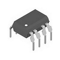
IL300-F-X006 Vishay, IL300-F-X006 Datasheet - Page 4

IL300-F-X006
Manufacturer Part Number
IL300-F-X006
Description
Optocoupler
Manufacturer
Vishay
Datasheet
1.IL300-F-X006.pdf
(11 pages)
Specifications of IL300-F-X006
Leaded Process Compatible
Yes
Current Transfer Ratio
0.5 % to 1.1 %
Forward Current
10 mA
Isolation Voltage
5300 Vrms
Maximum Fall Time
1.75 us
Maximum Rise Time
1.75 us
Output Device
PIN Photodiode
Output Type
DC
Configuration
1 Channel
Input Type
AC/DC
Maximum Forward Diode Voltage
1.5 V
Maximum Reverse Diode Voltage
5 V
Maximum Input Diode Current
60 mA
Maximum Power Dissipation
210 mW
Maximum Operating Temperature
+ 100 C
Minimum Operating Temperature
- 55 C
Package / Case
DIP-8
Number Of Elements
1
Reverse Breakdown Voltage
5V
Forward Voltage
1.5V
Collector-emitter Voltage
Not RequiredV
Package Type
PDIP
Collector Current (dc) (max)
Not RequiredA
Power Dissipation
210mW
Collector-emitter Saturation Voltage
Not RequiredV
Pin Count
8
Mounting
Through Hole
Operating Temp Range
-55C to 100C
Operating Temperature Classification
Industrial
Lead Free Status / RoHS Status
Lead free / RoHS Compliant
Lead Free Status / RoHS Status
Lead free / RoHS Compliant, Lead free / RoHS Compliant
Available stocks
Company
Part Number
Manufacturer
Quantity
Price
Part Number:
IL300-F-X006
Manufacturer:
VISHAY/威世
Quantity:
20 000
IL300
Vishay Semiconductors
Notes
(1)
(2)
(3)
(4)
www.vishay.com
4
ELECTRICAL CHARACTERISTCS
PARAMETER
COUPLER
Transfer gain stability
Transfer gain linearity
PHOTOCONDUCTIVE OPERATION
Frequency response
Phase response at 200 KHz
SWITCHING CHARACTERISTICS
PARAMETER
Switching time
Rise time
Fall time
COMMON MODE TRANSIENT IMMUNITY
PARAMETER
Common mode capacitance
Common mode rejection ratio
Minimum and maximum values were tested requierements. Typical values are characteristics of the device and are the result of engineering
evaluation. Typical values are for information only and are not part of the testing requirements.
Bin sorting:
K3 (transfer gain) is sorted into bins that are ± 6 % , as follows:
Bin A = 0.557 to 0.626
Bin B = 0.620 to 0.696
Bin C = 0.690 to 0.773
Bin D = 0.765 to 0.859
Bin E = 0.851 to 0.955
Bin F = 0.945 to 1.061
Bin G = 1.051 to 1.181
Bin H = 1.169 to 1.311
Bin I = 1.297 to 1.456
Bin J = 1.442 to 1.618
K3 = K2/K1. K3 is tested at I
Bin categories: All IL300s are sorted into a K3 bin, indicated by an alpha character that is marked on the part. The bins range from "A" through
"J".
The IL300 is shipped in tubes of 50 each. Each tube contains only one category of K3. The category of the parts in the tube is marked on
the tube label as well as on each individual part.
Category options: standard IL300 orders will be shipped from the categories that are available at the time of the order. Any of the ten
categories may be shipped. For customers requiring a narrower selection of bins, the bins can be grouped together as follows:
IL300-DEFG: order this part number to receive categories D, E, F, G only.
IL300-EF: order this part number to receive categories E, F only.
IL300-E: order this part number to receive category E only.
F
= 10 mA, V
For technical questions, contact:
det
I
ΔI
f = 60 Hz, R
Fq
= - 15 V.
V
Linear Optocoupler, High Gain
TEST CONDITION
I
F
TEST CONDITION
F
= 10 mA, MOD = ± 4 mA,
F
(1)
= 2 mA, I
T
= 10 mA, V
TEST CONDITION
= 0 V, f = 1 MHz
amb
Stability, Wide Bandwidth
I
I
F
(T
F
V
= 1 to 10 mA,
= 1 to 10 mA
= 0 °C to 75 °C
R
det
amb
L
L
= 50 Ω
= - 15 V
Fq
= 2.2 kΩ
= 25 °C, unless otherwise specified)
= 10 mA
det
= - 15 V
optocoupleranswers@vishay.com
SYMBOL
SYMBOL
BW (- 3 db)
SYMBOL
CMRR
ΔK3/ΔT
C
ΔK3
CM
t
t
t
t
r
f
r
f
A
MIN.
MIN.
MIN.
± 0.005
± 0.25
TYP.
TYP.
1.75
1.75
TYP.
± 0.5
130
0.5
- 45
200
1
1
Document Number: 83622
± 0.05
MAX.
MAX.
MAX.
Rev. 1.6, 10-Nov-10
%/°C
UNIT
UNIT
UNIT
Deg.
KHz
dB
pF
μs
μs
μs
μs
%
%


