HFBR-5208FM Avago Technologies US Inc., HFBR-5208FM Datasheet - Page 9
HFBR-5208FM
Manufacturer Part Number
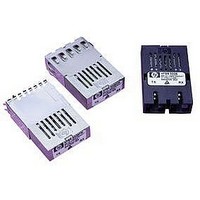
HFBR-5208FM
Description
Fiber Optics, Transceiver Module
Manufacturer
Avago Technologies US Inc.
Specifications of HFBR-5208FM
Peak Reflow Compatible (260 C)
No
Leaded Process Compatible
No
Connector Type
SC Duplex
Lead Free Status / RoHS Status
Contains lead / RoHS non-compliant


Table 1. Pinout Table
9
Pin
Mounting Studs
1
2
3
5
6
7
8
9
4
1 = V
2 = RD
3 = RD
4 = SD
5 = V
6 = V
7 = TD
8 = TD
9 = V
Symbol
RD+
RD-
SD
V
V
V
TD-
TD+
V
EER
CCR
CCT
EET
EER
CCR
CCT
EET
Functional Description
ground.
Receiver Signal Ground
Directly connect this pin to receiver signal ground plane. Receiver V
Receiver Data Out
input pin.
Receiver Data Out Bar
input pin.
Signal Detect
Normal input optical signal levels to the receiver result in a logic "1" output (V
Low input optical signal levels to the receiver result in a fault condition indication shown by a logic "0"
output (V
If Signal Detect output is not used, leave it open-circuited.
input or Loss of Signal-bar.
Receiver Power Supply
Provide +5 V dc via the recommended receiver V
Locate the power supply filter circuit as close as possible to the V
Provide +5 V dc via the recommended transmitter V
Locate the power supply filter circuit as close as possible to the V
transmitter input pin.
transmitter input pin.
Directly connect this pin to the transmitter signal ground plane. Transmitter V
TOP VIEW
The mounting studs are provided for transceiver mechanical attachment to the circuit boards, they are
embedded in the metalized plastic housing and are not connected to the transceiver internal circuit. They
should be soldered into plated-through holes on the printed circuit board and not connected to signal
common circuit board ground plane.
Terminate this high-speed, differential, PECL output with standard PECL techniques at the follow-on device
Terminate this high-speed, differential, PECL output with standard PECL techniques at the follow-on device
This Signal Detect output can be used to drive a PECL input on an upstream circuit, such as, Signal Detect
Transmitter Power Supply
Transmitter Data In Bar
Terminate this high-speed, differential, Transmitter Data input with standard PECL techniques at the
Transmitter Data In
Terminate this high-speed, differential, Transmitter Data input with standard PECL techniques at the
Transmitter Signal Ground
connect to a common circuit board ground plane.
N/C
N/C
OL
).
N/C = NO INTERNAL CONNECTION
(MOUNTING POSTS) - CONNECT
TO CHASSIS GROUND OR LEAVE
FLOATING, DO NOT CONNECT TO
SIGNAL GROUND.
CCR
power supply filter circuit.
CCT
power supply filter circuit.
CCR
CCT
EER
pin.
pin.
and transmitter V
EET
OH
).
and receiver V
EET
can connect to a
EER
can
Related parts for HFBR-5208FM
Image
Part Number
Description
Manufacturer
Datasheet
Request
R

Part Number:
Description:
RECEIVER FIBER OPTIC 600NM 40KBD
Manufacturer:
Avago Technologies US Inc.
Datasheet:

Part Number:
Description:
XMITTER FIBER OPTIC 600NM 5MBD
Manufacturer:
Avago Technologies US Inc.
Datasheet:

Part Number:
Description:
XMITTER FIBER OPTIC 600NM 40KBD
Manufacturer:
Avago Technologies US Inc.
Datasheet:

Part Number:
Description:
XMITTER VERSATILE LINK HORZ
Manufacturer:
Avago Technologies US Inc.
Datasheet:

Part Number:
Description:
XMITTER OPT HI PERFORMANCE VERT
Manufacturer:
Avago Technologies US Inc.
Datasheet:

Part Number:
Description:
TXRX FIBER OPTIC 650NM 10MBAUD
Manufacturer:
Avago Technologies US Inc.
Datasheet:
Part Number:
Description:
TXRX FIBER OPTIC 650NM 10MBAUD
Manufacturer:
Avago Technologies US Inc.
Datasheet:

Part Number:
Description:
FIBER OPTIC TRANSMITTER 660NM
Manufacturer:
Avago Technologies US Inc.
Datasheet:

Part Number:
Description:
KIT EVAL FIBER OPTIC 5MBD
Manufacturer:
Avago Technologies US Inc.
Datasheet:
Part Number:
Description:
KIT EVAL FIBER OPTICS 32MBD
Manufacturer:
Avago Technologies US Inc.
Datasheet:

Part Number:
Description:
KIT EVAL FIBER OPTIC 5MBD
Manufacturer:
Avago Technologies US Inc.
Datasheet:

Part Number:
Description:
125MBd 1300nm FiberOptic Eval Kit
Manufacturer:
Avago Technologies US Inc.
Datasheet:

Part Number:
Description:
DC-5MBd 820nm FiberOptic EvalKit
Manufacturer:
Avago Technologies US Inc.
Datasheet:
Part Number:
Description:
125MBd 820nm FiberOptic Eval Kit
Manufacturer:
Avago Technologies US Inc.
Datasheet:
Part Number:
Description:
DC-5MBd 650nm POF Eval Kit
Manufacturer:
Avago Technologies US Inc.
Datasheet: