AMMP-6545-TR2G Avago Technologies US Inc., AMMP-6545-TR2G Datasheet - Page 6
AMMP-6545-TR2G
Manufacturer Part Number
AMMP-6545-TR2G
Description
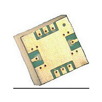
SubHarmonic Mixer 18-45GHz MMIC
Manufacturer
Avago Technologies US Inc.
Datasheet
1.AMMP-6545-TR2G.pdf
(7 pages)
Specifications of AMMP-6545-TR2G
Rf Type
DBS, LMDS, VSAT
Frequency
18GHz ~ 40GHz
Number Of Mixers
1
Package / Case
8-SMD
Lead Free Status / RoHS Status
Lead free / RoHS Compliant
Current - Supply
-
Voltage - Supply
-
Gain
-
Noise Figure
-
Secondary Attributes
-
Lead Free Status / Rohs Status
Compliant


Manual Assembly
x Follow ESD precautions while handling packages.
x Handling should be along the edges with tweezers.
x Recommended attachment is conductive solder
x Apply solder paste using a stencil printer or dot
x Follow solder paste and vendor’s recommendations
x Packages have been qualified to withstand a peak
Figure 14. Suggested lead-free reflow profile for SnAgCu solder paste
AMMP-6545 Part Number Ordering Information
6
Part Number
AMMP-6545-BLKG
AMMP-6545-TR1G
AMMP-6545-TR2G
paste. Please see recommended solder reflow profile.
Neither Conductive epoxy or hand soldering is
recommended.
placement. The volume of solder paste will be
dependent on PCB and component layout and
should be controlled to ensure consistent mechani-
cal and electrical performance.
when developing a solder reflow profile. A standard
profile will have a steady ramp up from room temper-
ature to the pre-heat temp. to avoid damage due to
thermal shock.
temperature of 260°C for 20 seconds. Verify that the
profile will not expose device beyond these limits.
300
250
200
150
100
50
0
0
RAMP 1
50
PREHEAT
100
10
Devices per
Container
100
500
RAMP 2
PEAK = 250 ± 5°C
TIME (SECONDS)
150
REFLOW
Antistatic bag
MELTING POINT = 218°C
Container
7” Reel
7” Reel
200
COOLING
250
A properly designed solder screen or stencil is required
to ensure optimum amount of solder paste is deposited
onto the PCB pads. The recommended stencil layout is
shown in Figure 13. The stencil has a solder paste depo-
sition opening approximately 70% to 90% of the PCB
pad. Reducing stencil opening can potentially generate
more voids underneath. On the other hand, stencil
openings larger than 100% will lead to excessive solder
paste smear or bridging across the I/O pads. Consid-
ering the fact that solder paste thickness will directly
affect the quality of the solder joint, a good choice is to
use a laser cut stencil composed of 0.127 mm (5 mils)
thick stainless steel which is capable of producing the
required fine stencil outline.
The most commonly used solder reflow method is ac-
complished in a belt furnace using convection heat
transfer. The suggested reflow profile for automated
reflow processes is shown in Figure 14. This profile is
designed to ensure reliable finished joints. However, the
profile indicated in Figure 1 will vary among different
solder pastes from different manufacturers and is shown
here for reference only.
300
Related parts for AMMP-6545-TR2G
Image
Part Number
Description
Manufacturer
Datasheet
Request
R

Part Number:
Description:
SubHarmonic Mixer 18-45GHz MMIC
Manufacturer:
Avago Technologies US Inc.
Datasheet:
Part Number:
Description:
SubHarmonic Mixer 18-45GHz MMIC
Manufacturer:
Avago Technologies US Inc.
Datasheet:

Part Number:
Description:
IC AMP GP HI PWR 6-20GHZ 8-SMD
Manufacturer:
Avago Technologies US Inc.
Datasheet:

Part Number:
Description:
IC AMP GP HI PWR 6-20GHZ 8-SMD
Manufacturer:
Avago Technologies US Inc.
Datasheet:

Part Number:
Description:
IC MMIC AMP HGA 6-20GHZ 8SMD
Manufacturer:
Avago Technologies US Inc.
Datasheet:

Part Number:
Description:
IC MMIC AMP HGA 6-20GHZ 8SMD
Manufacturer:
Avago Technologies US Inc.
Datasheet:
Part Number:
Description:
IC MMIC LOW NOISE 6-20GHZ 8-SMD
Manufacturer:
Avago Technologies US Inc.
Datasheet:
Part Number:
Description:
IC AMP GP HI PWR 6-20GHZ 8-SMD
Manufacturer:
Avago Technologies US Inc.
Datasheet:

Part Number:
Description:
6-20 GHz High Gain Amp In SMT Pkg
Manufacturer:
Avago Technologies US Inc.
Datasheet:

Part Number:
Description:
Power Amp, MMIC, 6-18GHz Pkg
Manufacturer:
Avago Technologies US Inc.
Datasheet:

Part Number:
Description:
OPTOCOUPLER GATE DRV 2A 16-SOIC
Manufacturer:
Avago Technologies US Inc.
Datasheet:
Part Number:
Description:
OPTOCOUPLER 2CH 2.5A 16-SOIC
Manufacturer:
Avago Technologies US Inc.
Datasheet:

Part Number:
Description:
OPTOCOUPLER GATE DRV 0.4A 16SOIC
Manufacturer:
Avago Technologies US Inc.
Datasheet:

Part Number:
Description:
OPTOCOUPLER 2.0A 250KHZ 8-DIP
Manufacturer:
Avago Technologies US Inc.
Datasheet:

Part Number:
Description:
OPTOCOUPLER 2.0A 250KHZ GW 8-SMD
Manufacturer:
Avago Technologies US Inc.
Datasheet: