AMMP-6545-TR2G Avago Technologies US Inc., AMMP-6545-TR2G Datasheet
AMMP-6545-TR2G
Specifications of AMMP-6545-TR2G


Related parts for AMMP-6545-TR2G


AMMP-6545-TR2G Summary of contents
Page 1
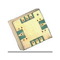
... GHz GaAs MMIC Sub-Harmonic Mixer in SMT Package Data Sheet Description Avago’s AMMP-6545 is an easy-to-use broadband sub-harmonic mixer, with the LO injected at half the frequency of that required by a conventional mixer. MMIC includes an 180° balanced diode based mixer. The MMIC is fabricated using PHEMT technology. The surface mount package allows elimination of “ ...
Page 2
... Symbol Parameter RFfreq RF Frequency LOfreq LO Frequency IFfreq IF Frequency LO LO Power Tmins Min. Ambient Operating Temp. Tmaxs Max. Ambient Operating Temp. AMMP-6545 RF Specifications T = 25° Ω +15 dBm GHz A o Symbol Parameter [1] CL Conversion Loss IIP3 Input Third Order Intercept 2LO-R 2LO-R Leakage ...
Page 3
... AMMP-6545 Typical Performance (T = 25° Ω), IF Freq = 2 GHz, LO Power = +15 dBm unless noted out UP-CONVERTER TYP. PERFORMANCE +13 (dB +15 (dB +17 (dB +19 (dB +20 (dB FREQUENCY (GHz) Figure 1. Up-conversion loss +13 to +20 dBm (high side LO) UP-CONVERTER TYP. PERFORMANCE +13 dBm +15 dBm +17 dBm LO = +19 dBm +20 dBm FREQUENCY (GHz) Figure 3 ...
Page 4
... IF Freq = 2 GHz, LO Power = +15 dBm unless noted out -30 -35 -40 -45 -50 -55 -60 -65 - FREQUENCY (GHz) Figure 7. 2*LO-R leakage +12 to +17 dBm FREQUENCY (GHz) Figure 9. L-R isolation +12 to +17dBm AMMP-6545 Application and Usage Figure 11. Simplified schematic of the mixer 4 -40 -45 -50 -55 -60 -65 - +12 dBm - +13 dBm LO = +14 dBm -80 ...
Page 5
... Recommended SMT Attachment for 5x5 Package The AMMP Packaged Devices are compatible with high volume surface mount PCB assembly processes. The PCB material and mounting pattern, as defined in the data sheet, optimizes RF performance and is strongly recommended. An electronic drawing of the land pattern is available upon request from Avago Sales & ...
Page 6
... Devices per Part Number Container AMMP-6545-BLKG 10 AMMP-6545-TR1G 100 AMMP-6545-TR2G 500 6 A properly designed solder screen or stencil is required to ensure optimum amount of solder paste is deposited onto the PCB pads. The recommended stencil layout is shown in Figure 13. The stencil has a solder paste depo- sition opening approximately 70% to 90% of the PCB pad ...
Page 7
... R 0.50 TYP. 1.75 ± 0.10 5.50 ± 0.05 Ø1.50 (MIN.) 8.00 ± 0. PITCH: WIDTH: Notes Pitches cumulative tolerance is ± 0.2 Mm. 3. Dimensions are in millimeters (mm). AMMP AMMP XXXX XXXX www.avagotech.com 0.114 (2.90) 0.018 (0.46) 0.014 (0.365 0.012 (0.30 0.028 (0.70) ...