AFBR-5715APZ Avago Technologies US Inc., AFBR-5715APZ Datasheet - Page 8
AFBR-5715APZ
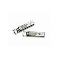
Manufacturer Part Number
AFBR-5715APZ
Description
Fiber Optic Transceiver,Module
Manufacturer
Avago Technologies US Inc.
Series
-r
Specifications of AFBR-5715APZ
Data Rate
1.25Gbps
Wavelength
850nm
Applications
Ethernet
Voltage - Supply
3.135 V ~ 3.465 V
Connector Type
LC Duplex
Mounting Type
SFP
Product
Transceiver
Maximum Rise Time
220 ps, 260 ps
Maximum Fall Time
220 ps, 260 ps
Pulse Width Distortion
0.227 ns, 0.266 ns
Operating Supply Voltage
3.135 V to 3.465 V
Maximum Operating Temperature
+ 85 C
Minimum Operating Temperature
- 40 C
Package / Case
SFP-20
Function
Designed for those applications requiring DMI features.
Lead Free Status / RoHS Status
Lead free / RoHS Compliant
For Use With
Multimode Glass
Lead Free Status / RoHS Status
Lead free / RoHS Compliant
Available stocks
Company
Part Number
Manufacturer
Quantity
Price
Company:

Part Number:
AFBR-5715APZ
Manufacturer:
Avago Technologies
Quantity:
135


Table 2. Pin Description
Notes:
1. TX Fault is an open collector/drain output which should be pulled up externally with a 4.7K – 10 K resistor on the host board to a supply
2. TX disable input is used to shut down the laser output per the state table below. It is pulled up within the module with a 4.7-10 K resistor.
3. Mod-Def 0,1,2. These are the module defi nition pins. They should be pulled up with a 4.7-10 K resistor on the host board to a supply less
4. LOS (Loss of Signal) is an open collector/drain output which should be pulled up externally with a 4.7 K – 10 K resistor on the host board to a
5. RD-/+: These are the diff erential receiver outputs. They are AC coupled 100 diff erential lines which should be terminated with 100 diff erential
6. VccR and VccT are the receiver and transmitter power supplies. They are defi ned as 3.135 – 3.465 V at the SFP connector pin. The in-rush current
7. TD-/+: These are the diff erential transmitter inputs. They are AC coupled diff erential lines with 100 diff erential termination inside the module.
8
Pin
1
2
3
4
5
6
7
8
9
10
11
12
13
14
15
16
17
18
19
20
<VccT+0.3 V or VccR+0.3 V. When high, this output indicates a laser fault of some kind. Low indicates normal operation. In the low state, the
output will be pulled to < 0.8 V.
than VccT +0.3 V or VccR+0.3 V.
supply < VccT,R+0.3 V. When high, this output indicates the received optical power is below the worst case receiver sensitivity (as defi ned by
the standard in use). Low indicates normal operatio0n. In the low state, the output will be pulled to < 0.8 V.
at the user SERDES. The AC coupling is done inside the module and is thus not required on the host board. The voltage swing on these lines
must be between 370 and 2000 mV diff erential (185 – 1000 mV single ended) according to the MSA. Typically it will be 1500mv diff erential.
will typically be no more than 30 mA above steady state supply current after 500 nanoseconds.
The AC coupling is done inside the module and is thus not required on the host board. The inputs will accept diff erential swings of 500 – 2400
mV (250 – 1200 mV single ended). However, the applicable recommended diff erential voltage swing is found in Table 5.
Mod-Def 0 is grounded by the module to indicate that the module is present
Mod-Def 1 is clock line of two wire serial interface for optional serial ID
Mod-Def 2 is data line of two wire serial interface for optional serial ID
Low (0 – 0.8 V):
Between (0.8 V and 2.0 V):
High (2.0 – 3.465 V):
Open:
Name
VeeT
TX Fault
TX Disable
MOD-DEF2
MOD-DEF1
MOD-DEF0
Rate Selection
LOS
VeeR
VeeR
VeeR
RD-
RD+
VeeR
VccR
VccT
VeeT
TD+
TD-
VeeT
Function/Description
Transmitter Ground
Transmitter Fault Indication
Transmitter Disable - Module disables on high or open
Module Defi nition 2 - Two wire serial ID interface
Module Defi nition 1 - Two wire serial ID interface
Module Defi nition 0 - Grounded in module
Not Connected
Loss of Signal
Receiver Ground
Receiver Ground
Receiver Ground
Inverse Received Data Out
Received Data Out
Reciver Ground
Receiver Power -3.3 V ±5%
Transmitter Power -3.3 V ±5%
Transmitter Ground
Transmitter Data In
Inverse Transmitter Data In
Transmitter Ground
Transmitter on
Undefi ned
Transmitter Disabled
Transmitter Disabled
Engagement
Order(insertion)
1
3
3
3
3
3
3
3
1
1
1
3
3
1
2
2
1
3
3
1
Notes
1
2
3
3
3
4
5
5
6
6
7
7
Related parts for AFBR-5715APZ
Image
Part Number
Description
Manufacturer
Datasheet
Request
R

Part Number:
Description:
TXRX OPT OC3 MTRJ SFF 2X5DIP
Manufacturer:
Avago Technologies US Inc.
Datasheet:

Part Number:
Description:
TXRX ETHERNET 125MBD MMF 2X5
Manufacturer:
Avago Technologies US Inc.
Datasheet:

Part Number:
Description:
TXRX OPT SFP DGTL 850NM IND
Manufacturer:
Avago Technologies US Inc.
Datasheet:

Part Number:
Description:
650nm FE Transceiver Eval Kit
Manufacturer:
Avago Technologies US Inc.
Datasheet:

Part Number:
Description:
TXRX OPT SFF 4/2/1GBD 2X7
Manufacturer:
Avago Technologies US Inc.
Datasheet:

Part Number:
Description:
TXRX OPT SFP 4/2/1GBD 850NM
Manufacturer:
Avago Technologies US Inc.
Datasheet:

Part Number:
Description:
TXRX OPT XFP 10GB/S 850NM
Manufacturer:
Avago Technologies US Inc.
Datasheet:

Part Number:
Description:
TXRX OPT 1X9 100MBPS ST EXT TEMP
Manufacturer:
Avago Technologies US Inc.
Datasheet:

Part Number:
Description:
TXRX OPT 1X9 100MBPS SC EXT TEMP
Manufacturer:
Avago Technologies US Inc.
Datasheet:

Part Number:
Description:
TXRX OPT 1X9 100MBPS DUPLEX SC
Manufacturer:
Avago Technologies US Inc.
Datasheet:

Part Number:
Description:
OPTOCOUPLER GATE DRV 2A 16-SOIC
Manufacturer:
Avago Technologies US Inc.
Datasheet:
Part Number:
Description:
OPTOCOUPLER 2CH 2.5A 16-SOIC
Manufacturer:
Avago Technologies US Inc.
Datasheet:

Part Number:
Description:
OPTOCOUPLER GATE DRV 0.4A 16SOIC
Manufacturer:
Avago Technologies US Inc.
Datasheet:

Part Number:
Description:
OPTOCOUPLER 2.0A 250KHZ 8-DIP
Manufacturer:
Avago Technologies US Inc.
Datasheet:

Part Number:
Description:
OPTOCOUPLER 2.0A 250KHZ GW 8-SMD
Manufacturer:
Avago Technologies US Inc.
Datasheet: