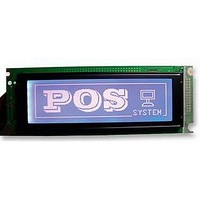
LMR4270EW-WCB DENSITRON, LMR4270EW-WCB Datasheet - Page 16

LMR4270EW-WCB
Manufacturer Part Number
LMR4270EW-WCB
Description
LCD MODULE, 64X240, BLUE
Manufacturer
DENSITRON
Datasheet
1.LMR4270BG-WCY.pdf
(47 pages)
Specifications of LMR4270EW-WCB
Lcd Display Type
STN
Pixel Size (h X W)
0.49mm X 0.49mm
Display Mode
Transmissive
Interface Type
Serial
Viewing Area (h X W)
39mm X 133mm
Supply Voltage
5V
External Depth
16mm
External Length /
RoHS Compliant
Svhc
No SVHC (15-Dec-2010)
Rohs Compliant
Yes
Backlighting Colour
White
Pixel Pitch (h X W)
0.53mm X 0.53mm
Setting registers
(1)Set Cursor Pointer
(2)Set Offset Register
The position of the cursor is specified by X ADRS and Y ADRS. The cursor position can only be
moved by this command. Data read/write from the MPU never changes the cursor pointer. X ADRS
and Y ADRS are specified as follows.
Single-Scan
X ADRS 00 to 4FH
The offset register is used to determine the external character generator RAM area.
The T6963C has a 16-bit address bus as follows.
T6963C assign External character generator, when character code set 80H TO FFH in using internal
character generator. Character code 00H to 80H assign External character generator, when External
generator mode.
The senior five bits define the start address in external memory of the CG RAM area. The next eight
X ADRS 00H to 4FH (lower 7 bits are valid)
Y ADRS 00H to 1FH (lower 5 bits are valid)
DENSITRON TECHNOLOGIES plc. – PROPRIETARY DATA – ALL RIGHTS RESERVED
Y ADRS 00H to 0FH
00100001
00100010
00100100
CODE
HEX.
21H
23H
24H
11111×101
11111×110
11111×111
SET CURSOR POINTER
SET OFFSET REGISTER
SET ADDRESS POINTER
FUNCTION
-
-
-
-
-
-
LOW ADRS HIGH ADRS
Bit 5
Bit 6
Bit 7 (MSB)
X ADRS
DATA
D1
Y ADRS
00H
D2
Page
X: invalid
16 / 47


