IL252 Vishay, IL252 Datasheet
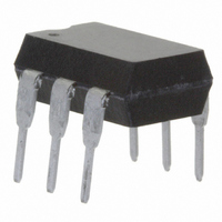
OPTOCOUPLER, PHOTOTRANSISTOR, 5300VRMS

IL252

Manufacturer Part Number
IL252
Description
OPTOCOUPLER, PHOTOTRANSISTOR, 5300VRMS
Manufacturer
Vishay
Datasheets

Specifications of IL252

No. Of Channels
1
Optocoupler Output Type
Phototransistor
Input Current
10mA
Output Voltage
30V
Opto Case Style
DIP
No. Of Pins
6
Mounting Type
Through Hole
Isolation Voltage
5.3kV
Number Of Channels
2
Input Type
AC, DC
Voltage - Isolation
5300Vrms
Current Transfer Ratio (min)
100% @ 10mA
Voltage - Output
30V
Current - Dc Forward (if)
60mA
Vce Saturation (max)
400mV
Output Type
Transistor with Base
Package / Case
6-DIP (0.300", 7.62mm)
Forward Current
60 mA
Maximum Input Diode Current
60 mA
Output Device
Transistor With Base
Configuration
1
Maximum Collector Emitter Voltage
30 V
Maximum Collector Emitter Saturation Voltage
400 mV
Maximum Forward Diode Voltage
1.5 V
Maximum Power Dissipation
400 mW
Maximum Operating Temperature
+ 100 C
Minimum Operating Temperature
- 55 C
Lead Free Status / RoHS Status
Lead free / RoHS Compliant
Current - Output / Channel
-
Current Transfer Ratio (max)
-
Lead Free Status / Rohs Status
Lead free / RoHS Compliant
Other names
751-1290-5
IL252GI
IL252GI

Available stocks

Company
Part Number
Manufacturer
Quantity
Price
Part Number:
IL252
Quantity:
2 470
Part Number:
IL252
Manufacturer:
SIEMENS/西门子
Quantity:
20 000
Part Number:
IL252-675
Quantity:
5 510
Part Number:
IL252-675
Quantity:
5 510
Part Number:
IL252-X001
Manufacturer:
INFINEON
Quantity:
1 423
Part Number:
IL252-X001
Manufacturer:
INTERSIL
Quantity:
1 424
Part Number:
IL252-X007T
Manufacturer:
VISHAY/威世
Quantity:
20 000
Company:
Part Number:
IL252-X017T
Quantity:
70 000
Company:
Part Number:
IL252-X017T
Quantity:
70 000
IL1, IL2, IL5
Vishay Semiconductors
DESCRIPTION
The IL1, IL2, IL5 are optically coupled isolated pairs
employing
phototransistor. Signal information, including a DC level, can
be transmitted by the drive while maintaining a high degree
of electrical isolation between input and output. The IL1, IL2,
IL5 are especially designed for driving medium-speed logic
and can be used to eliminate troublesome ground loop and
noise problems. These couplers can be used also to replace
relays and transformers in many digital interface applications
such as CRT modulation.
Note
For additional information on the available options refer to option information.
www.vishay.com
294
ORDER INFORMATION
PART
IL1
IL2
IL5
IL1-X006
IL2-X006
IL2-X009
IL5-X009
ABSOLUTE MAXIMUM RATINGS
PARAMETER
INPUT
Reverse voltage
Forward current
Surge current
Power dissipation
Derate linearly from 25 °C
OUTPUT
Collector emitter breakdown voltage
Emitter base breakdown voltage
Collector base breakdown voltage
Collector current
Power dissipation
Derate linearly from 25 °C
i179004
Optocoupler, Phototransistor Output, with Base Connection
GaAs
infrared
NC
LEDs
A
C
For technical questions, contact: optocoupler.answers@vishay.com
1
2
3
and
silicon
(1)
TEST CONDITION
6
5
4
t < 1.0 ms
B
C
E
NPN
FEATURES
• Current transfer ratio (see order information)
• Isolation test voltage 5300 V
• Lead (Pb)-free component
• Component in accordance to RoHS 2002/95/EC
AGENCY APPROVALS
• UL1577, file no. E52744 system code H or J, double
• DIN EN 60747-5-5 (VDE 0884) available with option 1
• BSI IEC 60950; IEC 60065
and WEEE 2002/96/EC
protection
PART
IL1
IL2
IL5
CTR > 100 %, DIP-6 400 mil (option 6)
CTR > 20 %, DIP-6 400 mil (option 6)
CTR >100 %, SMD-6 (option 9)
CTR > 50 %, SMD-6 (option 9)
CTR > 100 %, DIP-6
CTR > 20 %, DIP-6
CTR > 50 %, DIP-6
SYMBOL
BV
BV
BV
BV
BV
P
P
I
REMARKS
FSM
V
I
I
I
diss
diss
CEO
CEO
CEO
EBO
CBO
C
C
F
R
RMS
VALUE
Document Number: 83612
1.33
100
400
200
2.5
2.6
60
50
70
70
70
50
6
7
Rev. 1.6, 10-Dec-08
mW/°C
mW/°C
UNIT
mW
mW
mA
mA
mA
V
A
V
V
V
V
V

Related parts for IL252

IL252 Summary of contents

Page 1

... OUTPUT Collector emitter breakdown voltage Emitter base breakdown voltage Collector base breakdown voltage Collector current Power dissipation Derate linearly from 25 °C www.vishay.com For technical questions, contact: optocoupler.answers@vishay.com 294 FEATURES • Current transfer ratio (see order information • Isolation test voltage 5300 • ...

Page 2

... Minimum and maximum values are testing requirements. Typical values are characteristics of the device and are the result of engineering evaluation. Typical values are for information only and are not part of the testing requirements. Document Number: 83612 For technical questions, contact: optocoupler.answers@vishay.com Rev. 1.6, 10-Dec-08 Optocoupler, Phototransistor ...

Page 3

... P SATURATED V CE Current time Delay time Rise time Storage time V www.vishay.com For technical questions, contact: optocoupler.answers@vishay.com 296 Optocoupler, Phototransistor Output, with Base Connection TEST CONDITION PART IL1 = 10 mA 0.4 V IL2 CE IL5 IL1 = 10 mA IL2 CE IL5 IL1 = 10 mA 9.3 V IL2 ...

Page 4

... kHz iil1_01 Fig Non-Saturated Switching Schematic kHz iil1_02 Fig Saturated Switching Schematic Document Number: 83612 For technical questions, contact: optocoupler.answers@vishay.com Rev. 1.6, 10-Dec-08 Optocoupler, Phototransistor Output, with Base Connection TEST CONDITION PART IL1 = 0 1.0 kΩ, L IL2 = 1 IL5 IL1 = 0 1.0 kΩ, ...

Page 5

... I - LED Current (mA) iil1_07 F Fig Normalized Non-Saturated and Saturated CTR vs. LED Current www.vishay.com For technical questions, contact: optocoupler.answers@vishay.com 298 Optocoupler, Phototransistor Output, with Base Connection 10 100 Fig Normalized Non-Saturated and Saturated CTR vs. NCTR(SAT) NCTR 10 100 Fig Normalized Non-Saturated and Saturated CTR, ...

Page 6

... I - LED Current (mA) iil1_13 F Fig Collector Base Photocurrent vs. LED Current Document Number: 83612 For technical questions, contact: optocoupler.answers@vishay.com Rev. 1.6, 10-Dec-08 Optocoupler, Phototransistor Output, with Base Connection = 100 iil1_14 Fig Normalized Photocurrent vs. I 100 iil1_15 Fig Normalized Non-Saturated h 100 iil1_16 Fig ...

Page 7

... Option 6 0.407 (10.36) 0.391 (9.96) 0.307(7.8) 0.291(7.4) 0.400(10.16) 0.430 (10.92) 18493 www.vishay.com For technical questions, contact: optocoupler.answers@vishay.com 300 Optocoupler, Phototransistor Output, with Base Connection 2.5 2.0 1.5 1.0 100 Pin one 0.335 (8.50) ...

Page 8

... The Montreal Protocol (1987) and its London Amendments (1990) intend to severely restrict the use of ODSs and forbid their use within the next ten years. Various national and international initiatives are pressing for an earlier ban on these substances. Vishay Semiconductor GmbH has been able to use its policy of continuous improvements to eliminate the use of ODSs listed in the following documents. ...

Page 9

... Vishay disclaims any and all liability arising out of the use or application of any product described herein or of any information provided herein to the maximum extent permitted by law. The product specifications do not expand or otherwise modify Vishay’ ...

Related keywords