YD630M ETERNA, YD630M Datasheet - Page 2
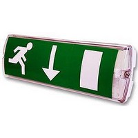
YD630M
Manufacturer Part Number
YD630M
Description
EMERGENCY LIGHT, MAINTAINED, 8W
Manufacturer
ETERNA
Datasheet
1.YD630M.pdf
(2 pages)
Specifications of YD630M
Length
345mm
Width
120mm
Depth
75mm
Ip/nema Rating
IP65
Svhc
No SVHC (15-Dec-2010)
Base Type
300mm T5 Fluorescent
External Depth
75mm
External Length / Height
345mm
External Width
120mm
Lamp Base Type
300mm T5 Fluorescent
Rohs Compliant
Yes
Lead Free Status / RoHS Status
Lead free / RoHS Compliant


Read this first:
>
>
>
>
>
>
>
>
>
>
>
>
Safety markings:
This light fitting must be installed in accordance
with the Building Regulations making reference
to the Wiring Regulations BS7671. The Building
Regulations may be obtained from HMSO or viewed
and downloaded from www.communities.gov.uk
following the link for Building Regulations.
Switch off the mains before commencing installation
and remove the appropriate circuit fuse.
Your emergency fittings should have their own
separate mains supply circuit and should not share
their supply with other lighting or electrical devices.
Suitable for indoor or outdoor use.
This product is suitable for installation on flammable
surfaces ( indicated by the "F" in a triangle )
Before making fixing hole(s), check that there are no
obstructions hidden beneath the mounting surface
such as pipes or cables.
The chosen location of your new fitting should allow
for the product to be securely mounted ( e.g. to a
ceiling joist ) and safely connected to the mains
supply ( lighting circuit ).
Ensure that the fitting will be accessible after
installation for maintenance.
If the location of your new fitting requires the
provision of a new electrical supply, the supply must
conform with the requirements of the Building
Regulations making reference to the Wiring
Regulations ( see above ).
Make connections to the electrical supply in
accordance with the following code:
This product must be connected to Earth.
You are advised at every stage of your installation to
double-check any electrical connections you have
made. After you have completed your installation
there are electrical tests that should be carried out:
these tests are specified in the Wiring Regulations
( BS7671 ) referred to in the Building Regulations. If
in doubt, consult a qualified electrician.
Live - Brown or Red
Neutral - Blue or Black
Earth - Green and Yellow
Installation:
1)
2)
3)
4)
5)
6)
7)
8)
9)
10) Thread the supply cable through the entry point and
11) Press the gear tray back into position on the hinge
12) To operate the fitting in non-maintained mode,
13) If the lamp is to be switched, remove the link from
14) Mark the current date on the battery pack.
15) Connect the battery pack to the circuit board.
16) Close the gear tray and press back onto the clips.
17) Replace the diffuser and tighten securely.
18) Restore the power supply. The LED should light to
Undo the screws at each end of the diffuser and lift
off.
Press the tabs protruding from the gear tray to open.
Gently prize one of the hinges off of its plastic pin
and lift off the gear tray.
Make the cable entry and fixing holes as required.
Inside the back of the fitting, there are markings to
assist you.
Using the back of the fitting as a template, mark the
position of the fixing holes on your mounting surface.
Make fixing holes and fit plugs as appropriate.
Secure the back of the fitting to the mounting surface
using suitable fixings ( not supplied ).
Apply a silicon sealant to the fixings if moisture or
weather-proofing is required.
Fitting a cable gland will also be necessary if
moisture or weather-proofing is required.
into the fitting.
pins and allow the gear tray to hang open. Make
connection to the mains supply according to the
colour code opposite. Take care not to leave any
strands protruding from the terminals and to tighten
all terminals securely. Ensure also that the terminals
clamp onto the bare wire and not onto the insulation.
remove the link from the terminals “SW”.
between the terminals marked “SW” and connect
cables to and from your switch.
indicate correct charging. If the link “SW” has been
left in place, the fitting should also light. If you have
connected a switch across the terminals “SW”, test
the operation of your switch.
IP65
Operation checks:
Periodic testing should be carried out monthly by
simulating a failure of supply, causing the fitting to be
energised from it’s battery. Interruption of the supply
should be carried out by the operation of a local keyswitch
or other isolation device. During this period all fittings
should be examined visually to ensure that they are
functioning correctly. At the end of the test period the
supply shall be restored and all indicator lamps or devices
checked to ensure that the normal supply has been
restored.
The duration of the simulated failure shall be:-
Each month:
Isolate the power supply and check the light is illuminated.
This test should last for no more than 45 minutes.
Endorse the test record form supplied.
Every six months:
Isolate the power supply and check that the light is still
illuminated after 1 hour. Endorse the test record form.
Once each year:
Isolate the power supply and check that the light is still
illuminated after 3 hours. Endorse the test record form.
Important notes:
Please keep this instruction booklet and test record in a
safe place. A fire officer or other authorised person may
want to see your record of inspection and testing.
The ballast and control gear must be operated only within
the enclosure supplied. The gear must not be operated
outside of the enclosure.
The battery charging circuit and DC ballast are separated
from the mains by at least basic ( single layer ) insulation.
When energised by a constant mains supply, the battery
will be constantly charged whether or not the lamp is
illuminated. On failure of the constant mains supply, the
fitting will switch automatically using transistorised
switching from battery charging to battery discharge
powering the lamp whether or not the lamp was
illuminated before the power failure. Both the mains and
battery supplies incorporate fuse protection: see fitting for
location and rating.
Related parts for YD630M
Image
Part Number
Description
Manufacturer
Datasheet
Request
R

Part Number:
Description:
LIGHT FITTING, CEILING, SLIM, 16W
Manufacturer:
ETERNA
Datasheet:

Part Number:
Description:
TRANSFORMER, 12V, 105VA, 5WAY
Manufacturer:
ETERNA
Datasheet:

Part Number:
Description:
PHOTOCELL, MINIATURE, REMOTE FIXING
Manufacturer:
ETERNA
Datasheet:

Part Number:
Description:
PHOTOCELL, NEMA, SOCKET
Manufacturer:
ETERNA
Datasheet:

Part Number:
Description:
PHOTOCELL, NEMA SOCKET KIT
Manufacturer:
ETERNA
Datasheet:

Part Number:
Description:
PHOTOCELL, WITH TIMER
Manufacturer:
ETERNA
Datasheet:

Part Number:
Description:
SWITCH, LIGHTING, AUTO
Manufacturer:
ETERNA
Datasheet:

Part Number:
Description:
PHOTOCELL, MINIATURE
Manufacturer:
ETERNA
Datasheet:


Part Number:
Description:
BRICK LIGHT, FRAMED
Manufacturer:
ETERNA
Datasheet:


Part Number:
Description:
BULKHEAD, GREY
Manufacturer:
ETERNA
Datasheet:

Part Number:
Description:
BULKHEAD, CORNER, BLK
Manufacturer:
ETERNA
Datasheet:
Part Number:
Description:
TRANSFORMER, 12V, 105VA, 5WAY
Manufacturer:
ETERNA
Datasheet: