TSOP1133 Vishay, TSOP1133 Datasheet - Page 4
TSOP1133
Manufacturer Part Number
TSOP1133
Description
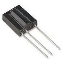
PHOTODIODE, IR RECEIVER, 33KHZ
Manufacturer
Vishay
Datasheet
1.TSOP1133.pdf
(7 pages)
Specifications of TSOP1133
Transmission Range
45m
Directivity
45°
Supply Voltage Range
2.5V To 5.5V
Opto Case Style
Through Hole
Operating Temperature Range
-25°C To +85°C
Carrier Frequency
33kHz
Supply Current
450µA
Lead Free Status / RoHS Status
Lead free / RoHS Compliant
Available stocks
Company
Part Number
Manufacturer
Quantity
Price

Company:
Part Number:
TSOP1133
Manufacturer:
NEC
Quantity:
17 600
Company:
Part Number:
TSOP1133TBT
Manufacturer:
TEMIC
Quantity:
14 838


TSOP11..
Vishay Semiconductors
www.vishay.com
4
16914
16918
94 8408
Figure 11. Relative Spectral Sensitivity vs. Wavelength
1.0
0.9
0.8
0.7
0.6
0.5
0.4
0.3
0.2
0.1
0.0
Figure 9. Max. Envelope Duty Cycle vs. Burstlength
0.6
0.5
0.4
0.3
0.2
0.1
0.0
1.2
1.0
0.8
0.6
0.4
0.2
Figure 10. Sensitivity vs. Ambient Temperature
–30 –15
0
0
750
Burst Length ( number of cycles / burst )
Sensitivity in dark ambient
T
20
amb
f = 38 kHz, E
850
– Ambient Temperature ( C )
0
l – Wavelength ( nm )
40
15
30
60
950
e
= 2 mW/m
45
80
60
1050
2
100
75
120
90
1150
Suitable Data Format
The circuit of the TSOP11.. is designed in that way
that unexpected output pulses due to noise or distur-
bance signals are avoided. A bandpass filter, an inte-
grator stage and an automatic gain control are used
to suppress such disturbances.
The distinguishing mark between data signal and dis-
turbance signal are carrier frequency, burst length
and duty cycle.
The data signal should fulfill the following conditions:
• Carrier frequency should be close to center fre-
quency of the bandpass (e.g. 38 kHz).
• Burst length should be 6 cycles/burst or longer.
• After each burst which is between 6 cycles and 70
cycles a gap time of at least 10 cycles is necessary.
95 11339p2
95 11340p2
1.0
0.9
1.0
0.9
0.8
0.7
0.8
0.7
0.6
0.6
d
d
rel
rel
Figure 12. Horizontal Directivity ϕ
0.4
0.4
Figure 13. Vertical Directivity ϕ
- Relative Transmission Distance
- Relative Transmission Distance
0.2
0.2
0°
0
0°
0
0.2
0.2
10°
10°
0.4
0.4
Document Number 82006
20°
20°
0.6
0.6
Rev. 12, 23-Jun-03
y
30°
40°
50°
60°
70°
80°
30°
40°
50°
60°
70°
80°
x
VISHAY
Related parts for TSOP1133
Image
Part Number
Description
Manufacturer
Datasheet
Request
R

Part Number:
Description:
Ir Receiver Modules For Remote Control Systems
Manufacturer:
Vishay
Datasheet:
Part Number:
Description:
357-036-542-201 CARDEDGE 36POS DL .156 BLK LOPRO
Manufacturer:
Vishay
Datasheet:
Part Number:
Description:
357-036-542-201 CARDEDGE 36POS DL .156 BLK LOPRO
Manufacturer:
Vishay
Datasheet:
Part Number:
Description:
357-036-542-201 CARDEDGE 36POS DL .156 BLK LOPRO
Manufacturer:
Vishay
Datasheet:
Part Number:
Description:
357-036-542-201 CARDEDGE 36POS DL .156 BLK LOPRO
Manufacturer:
Vishay
Datasheet:
Part Number:
Description:
357-036-542-201 CARDEDGE 36POS DL .156 BLK LOPRO
Manufacturer:
Vishay
Datasheet:
Part Number:
Description:
357-036-542-201 CARDEDGE 36POS DL .156 BLK LOPRO
Manufacturer:
Vishay
Datasheet:
Part Number:
Description:
357-036-542-201 CARDEDGE 36POS DL .156 BLK LOPRO
Manufacturer:
Vishay
Datasheet:
Part Number:
Description:
357-036-542-201 CARDEDGE 36POS DL .156 BLK LOPRO
Manufacturer:
Vishay
Datasheet:
Part Number:
Description:
357-036-542-201 CARDEDGE 36POS DL .156 BLK LOPRO
Manufacturer:
Vishay
Datasheet:
Part Number:
Description:
357-036-542-201 CARDEDGE 36POS DL .156 BLK LOPRO
Manufacturer:
Vishay
Datasheet:
Part Number:
Description:
357-036-542-201 CARDEDGE 36POS DL .156 BLK LOPRO
Manufacturer:
Vishay
Datasheet:
Part Number:
Description:
357-036-542-201 CARDEDGE 36POS DL .156 BLK LOPRO
Manufacturer:
Vishay
Datasheet:
Part Number:
Description:
357-036-542-201 CARDEDGE 36POS DL .156 BLK LOPRO
Manufacturer:
Vishay
Datasheet:
Part Number:
Description:
357-036-542-201 CARDEDGE 36POS DL .156 BLK LOPRO
Manufacturer:
Vishay
Datasheet: