TSOP1133 Vishay, TSOP1133 Datasheet - Page 2
TSOP1133
Manufacturer Part Number
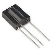
TSOP1133
Description
PHOTODIODE, IR RECEIVER, 33KHZ
Manufacturer
Vishay
Datasheet
1.TSOP1133.pdf
(7 pages)
Specifications of TSOP1133
Transmission Range
45m
Directivity
45°
Supply Voltage Range
2.5V To 5.5V
Opto Case Style
Through Hole
Operating Temperature Range
-25°C To +85°C
Carrier Frequency
33kHz
Supply Current
450µA
Lead Free Status / RoHS Status
Lead free / RoHS Compliant
Available stocks
Company
Part Number
Manufacturer
Quantity
Price

Company:
Part Number:
TSOP1133
Manufacturer:
NEC
Quantity:
17 600
Company:
Part Number:
TSOP1133TBT
Manufacturer:
TEMIC
Quantity:
14 838


TSOP11..
Vishay Semiconductors
Absolute Maximum Ratings
T
Electrical and Optical Characteristics
T
Typical Characteristics
www.vishay.com
2
V
V
V
Supply Voltage
Supply Current
Output Voltage
Output Current
Junction Temperature
Storage Temperature Range
Operating Temperature Range
Power Consumption
Soldering Temperature
Supply Current (Pin 2)
Supply Voltage (Pin 2)
Transmission Distance
Output Voltage Low (Pin 3)
Irradiance (30 - 40 kHz)
Irradiance (56 kHz)
Irradiance
Directivity
O
OH
OL
amb
amb
= 25 °C, unless otherwise specified
= 25 °C, unless otherwise specified
Optical Test Signal
(IR diode TSAL6200, I
Output Signal
t
d
1 )
*) t
t
Parameter
pi
pi
1 )
2 )
*)
w 6/fo is recommended for optimal function
3/f
t
pi
0
– 4/f
Parameter
< t
Figure 1. Output Function
d
0
< 9/f
t
< t
po
2 )
F
po
T
0
=0.4 A, N=6 pulses, f=f
< t
pi
+ 6/f
V
V
E
diode TSAL6200, I
I
f = f
Test signal see fig.1
Test signal see fig.3
Test signal see fig.1
Test signal see fig.3
Test signal see fig.1
Angle of half transmission
distance
0
OSL
S
S
v
= 0, test signal see fig. 3, IR
= 5 V, E
= 5 V, E
(T
o
= 0.5 mA, E
, test signal see fig.1
amb
Test condition
0
v
v
, T=10 ms)
= 25 °C unless otherwise specified)
= 0
= 40 klx, sunlight
(Pin 2)
(Pin 2)
(Pin 3)
(Pin 3)
(T
t ≤ 10 s, > 1 mm from case
t
14337
amb
e
= 0.7 mW/m
F
≤ 85 °C)
= 0.4 A
Test condition
2
,
Symbol
E
E
E
E
E
V
ϕ
e max
16907
I
I
V
e min
e min
e min
e min
OSL
SD
SH
d
1/2
S
Figure 2. Pulse Length and Sensitivity in Dark Ambient
0.35
0.30
0.25
0.20
0.15
0.10
0.05
0.00
0.1
Min
0.8
4.5
1.0
30
E
optical test signal, fig.1
e
Input Burst Duration
Output Pulse
– Irradiance ( mW/m
10.0
l = 950 nm,
Symbol
T
T
P
T
V
100.0 1000.010000.0
V
amb
I
I
T
0.35
0.45
0.40
± 45
O
stg
Typ.
S
tot
sd
O
1.2
1.5
0.4
S
35
j
- 0.3 to + 6.0
- 0.3 to + 6.0
- 25 to + 85
- 25 to + 85
2
Document Number 82006
)
Value
100
260
50
Max
250
5
5
1.5
5.5
0.6
0.5
0.7
0.6
Rev. 12, 23-Jun-03
VISHAY
mW/m
mW/m
mW/m
mW/m
W/m
Unit
mW
mA
mA
Unit
deg
°C
°C
°C
°C
mA
mA
mV
V
V
m
V
2
2
2
2
2
Related parts for TSOP1133
Image
Part Number
Description
Manufacturer
Datasheet
Request
R

Part Number:
Description:
Ir Receiver Modules For Remote Control Systems
Manufacturer:
Vishay
Datasheet:
Part Number:
Description:
357-036-542-201 CARDEDGE 36POS DL .156 BLK LOPRO
Manufacturer:
Vishay
Datasheet:
Part Number:
Description:
357-036-542-201 CARDEDGE 36POS DL .156 BLK LOPRO
Manufacturer:
Vishay
Datasheet:
Part Number:
Description:
357-036-542-201 CARDEDGE 36POS DL .156 BLK LOPRO
Manufacturer:
Vishay
Datasheet:
Part Number:
Description:
357-036-542-201 CARDEDGE 36POS DL .156 BLK LOPRO
Manufacturer:
Vishay
Datasheet:
Part Number:
Description:
357-036-542-201 CARDEDGE 36POS DL .156 BLK LOPRO
Manufacturer:
Vishay
Datasheet:
Part Number:
Description:
357-036-542-201 CARDEDGE 36POS DL .156 BLK LOPRO
Manufacturer:
Vishay
Datasheet:
Part Number:
Description:
357-036-542-201 CARDEDGE 36POS DL .156 BLK LOPRO
Manufacturer:
Vishay
Datasheet:
Part Number:
Description:
357-036-542-201 CARDEDGE 36POS DL .156 BLK LOPRO
Manufacturer:
Vishay
Datasheet:
Part Number:
Description:
357-036-542-201 CARDEDGE 36POS DL .156 BLK LOPRO
Manufacturer:
Vishay
Datasheet:
Part Number:
Description:
357-036-542-201 CARDEDGE 36POS DL .156 BLK LOPRO
Manufacturer:
Vishay
Datasheet:
Part Number:
Description:
357-036-542-201 CARDEDGE 36POS DL .156 BLK LOPRO
Manufacturer:
Vishay
Datasheet:
Part Number:
Description:
357-036-542-201 CARDEDGE 36POS DL .156 BLK LOPRO
Manufacturer:
Vishay
Datasheet:
Part Number:
Description:
357-036-542-201 CARDEDGE 36POS DL .156 BLK LOPRO
Manufacturer:
Vishay
Datasheet:
Part Number:
Description:
357-036-542-201 CARDEDGE 36POS DL .156 BLK LOPRO
Manufacturer:
Vishay
Datasheet: