TSOP2140SA1 Vishay, TSOP2140SA1 Datasheet - Page 4
TSOP2140SA1
Manufacturer Part Number
TSOP2140SA1
Description
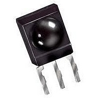
IR RECEIVER, 35M, 950NM, SIP
Manufacturer
Vishay
Datasheet
1.TSOP2140SA1.pdf
(7 pages)
Specifications of TSOP2140SA1
Transmission Range
35m
Directivity
45°
Supply Voltage Range
4.5V To 5.5V
Opto Case Style
Through Hole
Operating Temperature Range
-25°C To +85°C
Carrier Frequency
40kHz
Supply Current
1.4mA
Lead Free Status / RoHS Status
Lead free / RoHS Compliant


TSOP21..SA1
Vishay Semiconductors
Document Number 82160
Rev. 2, 15-Oct-2002
16914
16918
16919
Figure 11. Relative Spectral Sensitivity vs. Wavelength
Figure 9. Max. Envelope Duty Cycle vs. Burstlength
1.0
0.9
0.8
0.7
0.6
0.5
0.4
0.3
0.2
0.1
0.0
0.6
0.5
0.4
0.3
0.2
0.1
0.0
1.2
1.0
0.8
0.6
0.4
0.2
0.0
Figure 10. Sensitivity vs. Ambient Temperature
–30 –15
750
0
Burst Length ( number of cycles / burst )
Sensitivity in dark ambient
T
amb
20
f = 38 kHz, E
850
– Ambient Temperature ( C )
0
l – Wavelength ( nm )
40
15
950
30
60
e
= 2 mW/m
45
80
1050
60
2
100
75
1150
120
90
Suitable Data Format
The circuit of the TSOP21..SA1 is designed in that
way that unexpected output pulses due to noise or
disturbance signals are avoided. A bandpassfilter, an
integrator stage and an automatic gain control are
used to suppress such disturbances.
The distinguishing mark between data signal and dis-
turbance signal are carrier frequency, burst length
and duty cycle.
The data signal should fulfill the following conditions:
• Carrier frequency should be close to center fre-
quency of the bandpass (e.g. 38 kHz).
• Burst length should be 6 cycles/burst or longer.
• After each burst which is between 6 cycles and 70
cycles a gap time of at least 10 cycles is necessary.
• For each burst which is longer than 1.8 ms a corre-
sponding gap time is necessary at some time in the
data stream. This gap time should have at least same
length as the burst.
• Up to 2200 short bursts per second can be received
continuously.
Some examples for suitable data format are: NEC
Code, Toshiba Micom Format, Sharp Code, RC5
Code, RC6 Code, RCMM Code, R-2000 Code,
RECS-80 Code.
When a disturbance signal is applied to the
TSOP21..SA1 it can still receive the data signal. How-
ever the sensitivity is reduced to that level that no
unexpected pulses will occure.
Some examples for such disturbance signals which
are suppressed by the TSOP21..SA1 are:
• DC light (e.g. from tungsten bulb or sunlight)
• Continuous signal at 38 kHz or at any other fre-
quency
96 12223p2
1.0
0.9
0.8
0.7
0.6
d
rel
0.4
– Relative Transmission Distance
0.2
Figure 12. Directivity
0
0
0.2
10
0.4
20
0.6
30
40
50
60
70
80
www.vishay.com
VISHAY
4
Related parts for TSOP2140SA1
Image
Part Number
Description
Manufacturer
Datasheet
Request
R

Part Number:
Description:
TSOP 48/I�/8GX8 NAND FLASH PLASTIC IND TEMP PBF TSOP 3.3V ASYNCH/PAGE READ
Manufacturer:
Micron Semiconductor Products
Part Number:
Description:
TSOP 66/I�/64MX16 DDR SDRAM PLASTIC PBF TSOP 2.5V
Manufacturer:
Micron Semiconductor Products
Datasheet:
Part Number:
Description:
TSOP 54/I�/256MB 16MX16 SDRAM PLASTIC IND TEMP TSOP 3.3V
Manufacturer:
Micron Semiconductor Products
Datasheet:

Part Number:
Description:
TSOP/16MX16 SDRAM PLASTIC PBF TSOP 3.3V 200MHZ
Manufacturer:
Hynix Semiconductor
Part Number:
Description:
TSOP/16MX16 SDRAM PLASTIC PBF TSOP 3.3V 200MHZ
Manufacturer:
Hynix Semiconductor
Datasheet:
Part Number:
Description:
TSOP 66/C�/64MX8 DDR SDRAM PLASTIC PBF TSOP 2.6V tape and reel
Manufacturer:
Hynix Semiconductor

Part Number:
Description:
TSOP-1 48 12X20 CUSTD FLASH
Manufacturer:
NUMONYX
Datasheet:

Part Number:
Description:
TSOP, IND TEMP, GREEN(DATA FLASH)
Manufacturer:
ATMEL Corporation

Part Number:
Description:
Manufacturer:
Infineon Technologies
Datasheet:
Part Number:
Description:
Manufacturer:
Infineon Technologies
Datasheet:
Part Number:
Description:
Manufacturer:
Infineon Technologies
Datasheet:
Part Number:
Description:
Manufacturer:
Infineon Technologies
Datasheet:
Part Number:
Description:
Manufacturer:
Infineon Technologies
Datasheet: