PG12864LRF-NRA-H-Q POWERTIP, PG12864LRF-NRA-H-Q Datasheet - Page 26
PG12864LRF-NRA-H-Q
Manufacturer Part Number
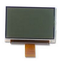
PG12864LRF-NRA-H-Q
Description
LCD MODULE, 128X64, LED B/L
Manufacturer
POWERTIP
Datasheet
1.PG12864LRF-NRA-H-Q.pdf
(29 pages)
Specifications of PG12864LRF-NRA-H-Q
Lcd Display Type
FSTN
Pixel Size (h X W)
0.28mm X 0.34mm
Viewing Area (h X W)
45.2mm X 27mm
Supply Voltage
3.3V
External Depth
6mm
External Length / Height
39mm
External
RoHS Compliant
Display Mode
Transflective


2.5.9 Display Timing Generator
2.5.10 Signal Generation to Display Line Counter, and Display Data Latching Circuit
0AH
0DH
3AH
3DH
0BH
0CH
0EH
3BH
3CH
3EH
00H
01H
02H
03H
04H
05H
06H
07H
08H
09H
0FH
10H
11H
35H
36H
37H
38H
39H
3FH
=1
=0
=1
=0
Both the clock to the line counter and latching signals to display data latching circuit from the display
clock (LP) are generated.
Synchronized with the display clock, the line addresses of Display RAM are generated and 128-bit
display data are latched to display-data latching circuit to output to the LCD driver circuit (SEG
output).
D
7
D
0
The display timing generator generates a timing clock necessary for internal operation and timing
pulses (LP, FLM, and M) by inputting the original oscillating clock CK or by the oscillating circuit of
OSC1 and OSC0.
By setting up Master/Stave mode(M/S), the state of timing pulse pins and the timing generator
changes.
D
6
D
1
D
5
D
2
X=0FH
X=00F
D
4
D
3
D
3
D
4
D
2
D
5
D
1
D
6
D
0
D
7
D
7
D
0
D
6
D
1
D
5
D
2
X=0EH
X=01H
DISPLAY DEVICES FOR BETTER ELECTRONIC DESIGN
D
4
D
3
POWERTIP TECHNOLOGY CORPORATION
D
3
D
4
D
2
D
5
D
1
D
6
D
0
D
7
…
…
…
…
…
…
D
7
D
0
D
6
D
1
D
5
D
2
X=0FH
X=00H
D
4
D
3
D
3
D
4
D
2
D
5
D
1
D
6
D
0
D
7
LINE
address
00H
01H
02H
03H
04H
05H
06H
07H
0AH
0BH
0CH
0DH
3AH
3BH
3CH
3DH
0EH
0FH
3EH
3FH
08H
09H
10H
11H
35H
36H
37H
38H
39H
COM0
COM1
COM2
COM3
COM4
COM5
COM6
COM7
COM8
COM9
COM10
COM11
COM12
COM13
COM14
COM15
COM16
COM17
COM53
COM54
COM55
COM56
COM57
COM58
COM59
COM60
COM61
COM62
COM63
Common
Output
Related parts for PG12864LRF-NRA-H-Q
Image
Part Number
Description
Manufacturer
Datasheet
Request
R

Part Number:
Description:
POWERTIP
Manufacturer:
Powertip Technology
Datasheet:
Part Number:
Description:
POWERTIP
Manufacturer:
Powertip Technology
Datasheet:
Part Number:
Description:
Powertip
Manufacturer:
Powertip Technology Corp.
Datasheet:
Part Number:
Description:
POWERTIP DISPL DEVICES FOR BET
Manufacturer:
Powertip Technology
Datasheet:
Part Number:
Description:
POWERTIP
Manufacturer:
Powertip Technology
Datasheet:
Part Number:
Description:
POWERTIP
Manufacturer:
Powertip Technology
Datasheet:
Part Number:
Description:
STANDARD VALUE
Manufacturer:
POWERTIP [Powertip Technology]
Datasheet:
Part Number:
Description:
OUTLINE DIMENSION & BLOCK DIAGRAM
Manufacturer:
POWERTIP [Powertip Technology]
Datasheet:
Part Number:
Description:
OUTLINE DIMENSION & BLOCK DIAGRAM
Manufacturer:
POWERTIP [Powertip Technology]
Datasheet:
Part Number:
Description:
OUTLINE DIMENSION & BLOCK DIAGRAM
Manufacturer:
POWERTIP [Powertip Technology]
Datasheet:
Part Number:
Description:
POWERTIP
Manufacturer:
Powertip Technology
Datasheet:
Part Number:
Description:
STANDARD VALUE
Manufacturer:
POWERTIP [Powertip Technology]
Datasheet:
Part Number:
Description:
OUTLINE DIMENSION & BLOCK DIAGRAM
Manufacturer:
POWERTIP [Powertip Technology]
Datasheet:
Part Number:
Description:
OUTLINE DIMENSION & BLOCK DIAGRAM
Manufacturer:
POWERTIP [Powertip Technology]
Datasheet:
Part Number:
Description:
Standard Value
Manufacturer:
Powertip Technology
Datasheet: