PG12864LRF-NRA-H-Q POWERTIP, PG12864LRF-NRA-H-Q Datasheet - Page 18
PG12864LRF-NRA-H-Q
Manufacturer Part Number
PG12864LRF-NRA-H-Q
Description
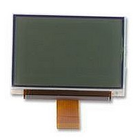
LCD MODULE, 128X64, LED B/L
Manufacturer
POWERTIP
Datasheet
1.PG12864LRF-NRA-H-Q.pdf
(29 pages)
Specifications of PG12864LRF-NRA-H-Q
Lcd Display Type
FSTN
Pixel Size (h X W)
0.28mm X 0.34mm
Viewing Area (h X W)
45.2mm X 27mm
Supply Voltage
3.3V
External Depth
6mm
External Length / Height
39mm
External
RoHS Compliant
Display Mode
Transflective


2-4.11 Power Control Register Set (1)
2-4.12 Power Control Register Set (2)
(At the time of reset: BIAS,HLT PON, ACL)=0H, read address: BH)
(1) ACL Command
(2) PON Command
(3) HALT Command
(4) BIAS Command
(At the time of reset:DVOL)=0H, read address: DH
The LCD drive voltage V0 output from the built-in power circuit can be controlled and the display
controlled and the display tone on the LCD can be also controlled.
The LCD drive V0 takes one out of 16 voltage values by setting 4 bit data register.
RE
RE
0
0
The internal circuit can be initiallized. This command is enabled only at Master operation mode.
ACL=”0”:Normal operation
ACL=”1”:Initialization ON
If the power control register is read out immediately after executing ACL command (ACL=1), the
D0 bit becomes “0”.
In executing ACL command, the internal reset signals are internary generated by using
display-clock onginal oscillation (oscillation by OSC1 and OSC0, or clock input at CK pin).
Therefore, after execuiting ACL command, allow WAIT period having at least two cycle portion
of the original oscillation clock before the next processing is made.
The internal power supply for the Graphic Display circult is set ON/OFF.
PON=”0: Power supply for the Graphic Display circuit OFF
PON=”1: Power supply for the Graphic Display circuit ON
At PON=”1”: the booster and volage converter for the Graphic Display circuit function.
In accordance with the setting conditions of PMODE pin, the operative circuit part changes. See
the Function Description in detall.
The conditions of power-saving are set ON/OFF by this command.
HALT=”0”: Nornal operation
HALT=”1”: Power-saving operation
When setting in the power-saving state, the consumed current can be reduced to a value near to
the stanby current. The intrnal conditions at power-saving are as follows.
(a) The oscillating circuit and power supply circuit are stopped.
(b) The LCD drive is stopped, and output of the segment drive and common driver are VSS lovel.
(c) The clock input from CK pin is inhibited.
(d) The contents of the Display RAM data are mintained.
(e) The operational mode maintains the state of command execution before executing
The internal bias value for the Graphic display can be set by this command.
BIAS=”0”: 1/9 bias
BIAS=”1”: 1/7 bias
(Bias value for the Segment Display is 1/3 Fixed)
power-saving command.
RS
RS
1
1
D7
D7
1
1
DISPLAY DEVICES FOR BETTER ELECTRONIC DESIGN
POWERTIP TECHNOLOGY CORPORATION
D6
D6
0
1
D5
D5
1
0
D4
D4
1
1
BIAS
MSS
D3
D3
……
HALT
D2
D2
LSB
PON
D1
D1
ACL
D0
D0
Related parts for PG12864LRF-NRA-H-Q
Image
Part Number
Description
Manufacturer
Datasheet
Request
R

Part Number:
Description:
POWERTIP
Manufacturer:
Powertip Technology
Datasheet:
Part Number:
Description:
POWERTIP
Manufacturer:
Powertip Technology
Datasheet:
Part Number:
Description:
Powertip
Manufacturer:
Powertip Technology Corp.
Datasheet:
Part Number:
Description:
POWERTIP DISPL DEVICES FOR BET
Manufacturer:
Powertip Technology
Datasheet:
Part Number:
Description:
POWERTIP
Manufacturer:
Powertip Technology
Datasheet:
Part Number:
Description:
POWERTIP
Manufacturer:
Powertip Technology
Datasheet:
Part Number:
Description:
STANDARD VALUE
Manufacturer:
POWERTIP [Powertip Technology]
Datasheet:
Part Number:
Description:
OUTLINE DIMENSION & BLOCK DIAGRAM
Manufacturer:
POWERTIP [Powertip Technology]
Datasheet:
Part Number:
Description:
OUTLINE DIMENSION & BLOCK DIAGRAM
Manufacturer:
POWERTIP [Powertip Technology]
Datasheet:
Part Number:
Description:
OUTLINE DIMENSION & BLOCK DIAGRAM
Manufacturer:
POWERTIP [Powertip Technology]
Datasheet:
Part Number:
Description:
POWERTIP
Manufacturer:
Powertip Technology
Datasheet:
Part Number:
Description:
STANDARD VALUE
Manufacturer:
POWERTIP [Powertip Technology]
Datasheet:
Part Number:
Description:
OUTLINE DIMENSION & BLOCK DIAGRAM
Manufacturer:
POWERTIP [Powertip Technology]
Datasheet:
Part Number:
Description:
OUTLINE DIMENSION & BLOCK DIAGRAM
Manufacturer:
POWERTIP [Powertip Technology]
Datasheet:
Part Number:
Description:
Standard Value
Manufacturer:
Powertip Technology
Datasheet: