SHL-W155 Omron, SHL-W155 Datasheet - Page 7
SHL-W155
Manufacturer Part Number
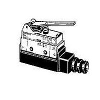
SHL-W155
Description
LIMIT SWITCH
Manufacturer
Omron
Series
SHLr
Type
Basicr
Datasheet
1.SHL-W255-01.pdf
(9 pages)
Specifications of SHL-W155
Circuit
SPDT
Switch Function
On-Mom
Contact Rating @ Voltage
10A @ 125VAC
Actuator Type
Lever, Straight
Mounting Type
Chassis Mount
Termination Style
Screw Terminal
Operating Force
235gf
Actuator
Lever
Contact Form
SPDT
Ip Rating
IP 67
Contact Rating
10 Amps at 120 VoltsAC, 240 VoltsAC
Ingress Protection
IP67
Mounting
Chassis
Lead Free Status / RoHS Status
Lead free / RoHS Compliant
Lead Free Status / RoHS Status
Lead free / RoHS Compliant
Other names
SHLW155


Safety Precautions
Refer to Safety Precautions for All Limit Switches.
Operating Environment
Connections
Be sure to connect a fuse with a breaking current 1.5 to 2 times the
rated current to the Limit Switch in series in order to protect the Limit
Switch from damage due to short-circuiting.
When using the Limit Switch under the EN ratings, use a gI or gG 10-
A fuse that conforms to IEC60269.
Mounting
• Seal material may deteriorate if a Switch is used outdoor or where
• Install Switches where they will not be directly subject to cutting
• Constantly subjecting a Switch to vibration or shock can result in
• The Switches have physical contacts. Using them in environments
• Secure the Switch with two M4 screws and washers.
• When mounting the panel mount-type Switch with screws on a side
• When mounting the panel mount type (SHL-Q55, SHL-Q2255, or
subject to special cutting oils, solvents, or chemicals. Always
appraise performance under actual application conditions and set
suitable maintenance and replacement periods.
chips, dust, or dirt. The Actuator and Switch must also be protected
from the accumulation of cutting chips or sludge.
wear, which can lead to contact interference with contacts,
operation failure, reduced durability, and other problems.
Excessive vibration or shock can lead to false contact operation or
damage. Install Switches in locations not subject to shock and
vibration and in orientations that will not produce resonance.
containing silicon gas will result in the formation of silicon oxide
(SiO
contacts, contact interference can occur. If silicon oil, silicon filling
agents, silicon cables, or other silicon products are present near the
Switch, suppress arcing with contact protective circuits (surge
killers) or remove the source of silicon gas.
The tightening torque applied to each terminal must be 1.18 to
1.37 N·m. Tighten the screws to the specified torque. An excessive
tightening torque may damage the Switch and cause a malfunction.
surface, remove the hexagonal nuts from the actuator.
SHL-Q2155) on a panel, tighten the hexagonal nuts of the actuator
to a torque less than 4.90 to 7.84 N·m.
Mounting Holes
Mounting Holes
Not Suitable
2
) due to arc energy. If silicon oxide accumulates on the
Precautions for Correct Use
16.5 ± 0.2
Two, 4.3-dia. or
M4 screw holes
14.5
+0.2
0
dia.
Suitable
Micro Load Models
When using a Limit Switch for opening or closing micro-load circuit
(zones 1 through 3), contact failure may occur if a Limit Switch with
ordinary contact specifications is used. Therefore, when using Limit
Switches in the micro-load range, use ones with contact
specifications that are suited to each zone. Use the SHL-@-01 micro
load models within the zones (1 through 3) shown in the following
diagram.
Micro Load Applicable Ranges
The above diagram is for standard conditions (+5°C to +35°C, 40% to
70%RH). Since the values vary depending on the operating
environment conditions, contact your OMRON representative for
further details.
Tightening Torque
Operating Stroke
Ensure that the operating stroke for roller plunger models is within
the set position display.
Others
The standard seal rubber for the lead wire outlet is one that allows 6-
to 8-dia. cables. The appropriate nominal cross-section of the lead
wire is 0.75 mm
period of time, use mold specifications.)
• A loose screw may result in a malfunction. Be sure to tighten each
• When wiring, use M3 round solderless terminals and apply
No.
screw to the proper tightening torque as shown below.
insulation shielding to the connections. Tighten the terminals
screws to 0.24 to 0.44 N·m.
1
2
Terminal screw (M3 screw)
30
24
12
2
Mounting screw
5
0
. (When the sealing capability is required over a long
0.1
Reference
Unusable
range
(M4 screw)
5 mW
0.16 mA
Type
1 mA
1
Operating range for
micro-load models
10
800 mW
26 mA
100 mA 160 mA
Appropriate tightening
Operating stroke
range
100
0.24 to 0.44 N·m
1.18 to 1.37 N·m
Current (mA)
Operating
range for
standard
models
torque
1,000
SHL
7
Related parts for SHL-W155
Image
Part Number
Description
Manufacturer
Datasheet
Request
R

Part Number:
Description:
L.S.,PLUNGER,PNL MNT
Manufacturer:
Omron
Datasheet:

Part Number:
Description:
G6S-2GLow Signal Relay
Manufacturer:
Omron Corporation
Datasheet:
Part Number:
Description:
Compact, Low-cost, SSR Switching 5 to 20 A
Manufacturer:
Omron Corporation
Datasheet:
Part Number:
Description:
Manufacturer:
Omron Corporation
Datasheet:
Part Number:
Description:
Manufacturer:
Omron Corporation
Datasheet:
Part Number:
Description:
Manufacturer:
Omron Corporation
Datasheet:
Part Number:
Description:
Manufacturer:
Omron Corporation
Datasheet:
Part Number:
Description:
Manufacturer:
Omron Corporation
Datasheet:
Part Number:
Description:
Manufacturer:
Omron Corporation
Datasheet: