H3CA-FA Omron, H3CA-FA Datasheet - Page 2
H3CA-FA
Manufacturer Part Number
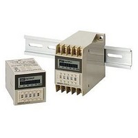
H3CA-FA
Description
Solid State Relay
Manufacturer
Omron
Datasheet
1.H3CA-8H_AC200220240.pdf
(16 pages)
Specifications of H3CA-FA
Contact Configuration
SPDT
Timing Adjustment
Pushbutton Thumbwheel
Relay Mounting
DIN Rail
Rohs Compliant
Yes
Lead Free Status / RoHS Status
Lead free / RoHS Compliant
Lead Free Status / RoHS Status
Lead free / RoHS Compliant, Lead free / RoHS Compliant
Other names
H3CAFA


■ Ratings
Note: 1. Single-phase, full-wave rectified power sources may be used for 24 to 240 VDC.
■ Characteristics
Accuracy of operating
time
Influence of voltage
Influence of
temperature
Setting error
Reset time
Insulation resistance
Dielectric strength
Impulse withstand
voltage
Vibration resistance
Shock resistance
Ambient temperature
Ambient humidity
Life expectancy
Approved standards
EMC
Weight
Rated supply voltage
(See note 2.)
Operating voltage range
Power consumption
Control outputs
2. Refer to Safety Precautions for All Times when combining the Timer with an AC 2-wire proximity sensor.
Item
±0.3% ±0.05 s
±0.5% ±0.05 s max.
H3CA-A/-FA: 0.5 s max.
H3CA-8H/-8: 0.1 s max.
100 MΩ min. (at 500 VDC)
2,000 VAC, 50/60 Hz for 1 min (between current-carrying and non-current-carrying parts and between contact and
control circuit)
1,000 VAC, 50/60 Hz for 1 min (between non-continuous contacts)
3 kV
Destruction: 10 to 55 Hz with 0.75-mm double amplitude for 1 h each in three directions
Malfunction: 10 to 55 Hz with 0.5-mm double amplitude for 10 min each in three directions
Destruction: 980 m/s
Malfunction: 98 m/s
Operating: –10°C to 55°C
Operating: 35% to 85%
Mechanical: 10,000,000 operations min. (under no load at 1,800 operations/h)
Electrical:
UL508, CSA C22.2 No. 14, LR, NK
Conforms to EN61010-1.
(EMI)
Emission Enclosure:
Emission AC mains:
(EMS)
Immunity ESD:
Immunity RF-interference:
Immunity Conducted
Disturbance:
Immunity Burst:
Immunity Surge:
Immunity Voltage Dip/Interruption
H3CA-A:
H3CA-FA: approx. 190 g
24 to 240 VAC (50/60 Hz),
12 to 240 VDC (permissible ripple:
20% max.)
90% to 110% of rated supply voltage 85% to 110% of rated supply voltage
AC: approx. 4 VA
DC: approx. 2 W
3 A at 250 VAC, resistive load (cosφ = 1)
approx. 110 g
100,000 operations min. (3 A at 250 VAC, cosφ = 1 at 1,800 operations/h)
See Lift-test Curve for more details.
H3CA-A/H3CA-FA
2
2
EN61326
EN55011 Group 1 class A
EN55011 Group 1 class A
EN61326
EN61000-4-2:
EN61000-4-3:
EN61000-4-6:
EN61000-4-4:
EN61000-4-5:
EN61000-4-11:
100/110/120, 200/220/240 VAC, (50/60 Hz),
24 VDC, 110 VDC (permissible ripple: 20% max.) (See note 1.)
AC: approx. 10 VA/1 W
DC: approx. 1 W
4 kV contact discharge (level 2)
8 kV air discharge (level 3)
10 V/m (Amplitude-modulated, 80 MHz to 1 GHz) (level 3);
10 V/m (Pulse-modulated, 900 MHz ±5 MHz) (level 3)
10 V (0.15 to 80 MHz) (according to EN61000-6-2)
2 kV power-line (level 3);
1 kV I/O signal-line (level 4)
1 kV line to lines (power and output lines) (level 3);
2 kV line to ground (power and output lines) (level 3)
0.5 cycle, 100% (rated voltage)
H3CA-8
AC: approx. 10 VA/1.5 W
DC: approx. 2 W
H3CA-8H
H3CA
2
Related parts for H3CA-FA
Image
Part Number
Description
Manufacturer
Datasheet
Request
R

Part Number:
Description:
RELAY DIGITAL SP 100/110/120VAC
Manufacturer:
Omron
Datasheet:

Part Number:
Description:
RELAY TIMER SSR SPDT 24V
Manufacturer:
Omron
Datasheet:
Part Number:
Description:
RELAY DIGITAL DP 100/110/120VAC
Manufacturer:
Omron
Datasheet:

Part Number:
Description:
SOLID STATE TIMER
Manufacturer:
Omron
Datasheet:

Part Number:
Description:
TIMER SOLID STATE W/LOCK MECH
Manufacturer:
Omron
Datasheet:

Part Number:
Description:
SOLID STATE TIMER, SPDT, 9990H, 120VAC
Manufacturer:
Omron
Datasheet:

Part Number:
Description:
G6S-2GLow Signal Relay
Manufacturer:
Omron Corporation
Datasheet:
Part Number:
Description:
Compact, Low-cost, SSR Switching 5 to 20 A
Manufacturer:
Omron Corporation
Datasheet:
Part Number:
Description:
Manufacturer:
Omron Corporation
Datasheet: