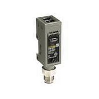
E3S-CL2 Omron, E3S-CL2 Datasheet - Page 7

E3S-CL2
Manufacturer Part Number
E3S-CL2
Description
50CM, ADJ SENSING DIST, NPN/PNP
Manufacturer
Omron
Series
E3S-CLr
Specifications of E3S-CL2
Rohs Compliant
YES
Sensing Distance
0.197" ~ 7.874" (5mm ~ 200mm) ADJ
Sensing Method
Reflective, Diffuse
Sensing Object
Black Paper, White Paper
Output Configuration
NPN/PNP - Dark-ON/Light-ON - Selectable
Sensing Light
Infrared
Mounting Type
Bracket Mount
Current - Supply
35mA
Voltage - Supply
10 V ~ 30 V
Package / Case
Module, Pre-Wired
Features
NPN/PNP Selectable Output
Sensing Range
50mm To 500mm
Sensor Output
Open Collector
Supply Voltage Range Dc
10V To 30V
Lead Free Status / RoHS Status
Lead free / RoHS Compliant
Lead Free Status / RoHS Status
Lead free / RoHS Compliant
Available stocks
Company
Part Number
Manufacturer
Quantity
Price
Company:
Part Number:
E3S-CL2
Manufacturer:
OMRON
Quantity:
475
H
Note: The sensor must be set to within the rated detection range for application (see diagrams on next page).
H
E3S-CL1
Note: Reflection rates are given in parentheses.
Item
Adjustment
procedure
Detecting
condition
Status of
distance
setting knob
and distance
setting
indicator
Indicators
E3S-CL
SENSITIVITY ADJUSTMENT
SET DISTANCE INDICATOR SCALE VS. DETECTION
DISTANCE CHARACTERISTIC (TYPICAL)
(min.)
30
20
10
Background interference can be a problem if the distance is set near the maximum value (5 to 6 on the scale). Factory settings are
as follows:
E3S-CL1: 20 cm (on white paper)
E3S-CL2: 50 cm (on white paper)
Set distance indicator scale
0
Rated
detection
range
Position A
Place the detected object at the
desired location and turn the
adjustment knob clockwise until the
LIGHT indicator (orange) lights. This
is position A.
1
OFF
2
Photoelectric sensor
White paper
(90%)
3
STABILITY
(green)
4
5
Black
paper
(5%)
6
ON
(max.)
LIGHT
(orange)
E3S-CL2
Position B and C
Background Object
Remove the detected object and turn the
adjustment knob clockwise until the LIGHT
indicator (orange) lights. This is position B.
Then turn the adjustment knob
counterclockwise until the LIGHT indicator
(orange) goes out. This is position C.
No Background Object
The maximum adjustment setting is used
as position C.
150
100
OFF
(min.)
50
Photoelectric sensor
Set distance indicator scale
STABILITY
(green)
0
Rated
detection
range
1
8
2
OFF
3
4
White paper
(90%)
LIGHT
(orange)
5
Black
paper
(5%)
6
(max.)
Setting
Set the adjustment to halfway
between A and C. Confirm that the
STAB indicator (green) remains lit
both with the detected object
present and not present. If the
STAB indicator does not remain lit,
reconsider the detection method to
enable stable operation.
---
ON
STABILITY
(green)
OFF
E3S-CL
LIGHT
(orange)


