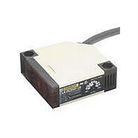
E3JK-R4M2-US Omron, E3JK-R4M2-US Datasheet - Page 11

E3JK-R4M2-US
Manufacturer Part Number
E3JK-R4M2-US
Description
UL/CSA MARK-RETRO
Manufacturer
Omron
Datasheet
1.E3JK-R4M2-US.pdf
(13 pages)
Specifications of E3JK-R4M2-US
Rohs Compliant
YES
Sensing Range
0m To 4m
Output Current
3A
Sensor Output
Relay
Lead Free Status / RoHS Status
Lead free / RoHS Compliant
Lead Free Status / RoHS Status
Lead free / RoHS Compliant
Other names
E3JKR4M2US
* These parts are not provided with models with a -US suffix.
● Wiring
Connecting and Wiring
Cable End Treatment
Adjust the four wires to the same length when
the Ta output is to be used only. If both the Ta
and Tb outputs are to be used, treat them as
shown in the following diagram.
Recommended example
Recommended Crimp Terminal Dimensions
Note: Use terminals with insulation tube (recommended crimp terminal: 1.25 to
● Others
Terminal Protection Cover (Provided)
The terminal protection cover is designed to improve safety by
maintaining the sensitivity properties of the product and by preventing
any contact with charged sections while it is being operated with the
mode set to the timer mode. Mount the product as shown in the
following diagram (mount the Through-beam Model on the Receiver
side).
• Recommended outer diameter of cables is from 6 to 8 mm.
• Be sure to firmly tighten the cover in order to maintain waterproof
7 max.
and dustproof properties. The screw size of the conduit sockets is
shown in the following table.
3.6 dia. min.
3.5).
Approx.
45 mm
Approx.
55 mm
Round type
E3JM-@
Model
19 max.
10 max.
Power
source
Tc, Ta
Tb
(After crimping)
7 max.
Tightening nut (provided)*
7 max.
E3JM
Conduit socket thread size
3.6 dia. min.
Terminal protection cover
Washer (provided)*
Rubber bushing (provided)*
Fork type
PF1/2
19 max.
10 max.
(After crimping)
(Unit: mm)
7 max.
● Designing
Power Reset Time
The Sensor is ready to detect within 200 ms after it is turned ON. If
the Sensor and load are connected to separate power supplies, be
sure to turn ON the Sensor first.
● Wiring
Connecting and Wiring DC SSR Output Models
When using the DC SSR output model, the total of the load current for
the Light-ON output (NO) and that for the Dark-ON (NC) should be
100 mA max. If the total exceeds 100 mA, the load short-circuit
protection function will be activated (this function will be reset when
the power of the Photoelectric Sensor is turned OFF).
● Others
Ambient Conditions (Installation Area)
The E3JM will malfunction if installed in the following places.
• Places where the E3JM is exposed to a dusty environment.
• Places where corrosive gases are produced.
• Places where the E3JM is directly exposed to water, oil, or
chemicals.
Items Common to
E3JM and E3JK
E3JK
E3JM/E3JK
11


