E3JK-R4M2-US Omron, E3JK-R4M2-US Datasheet
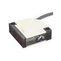
E3JK-R4M2-US
Specifications of E3JK-R4M2-US


Related parts for E3JK-R4M2-US


E3JK-R4M2-US Summary of contents
Page 1
... Note, however, that DC-type E3JK SSR Output Models are not UL-listed. *1. The model number of the Emitter is E3JK-5L 2M for all models. In order from the top of the model number of the Receivers are E3JK-5DM1 2M, E3JK-5DM2 2M, and E3JK-5DS3 2M. Orders for individual Emitters and Receivers are accepted. ...
Page 2
... E39-RS3 1.5 m (200 mm) * Quantity Remarks 1 Provided with the E3JM. 1 Provided with the E3JK. Mounting Bracket designed for changing 1 from he E3A-M, E3A2, E3A3, OA-5, or OA-5N to the E3JM. E3JM/E3JK Quantity Remarks (Seal-type long slit) Can be used with the E3JM-10@4(T) and E3JK-5@@ Through-beam Mod- els ...
Page 3
... Opaque: 75-mm dia. min. --- 1° to 5° Red LED (660 nm max max. --- 2 3 times each and Z directions 2 3 times each and Z directions Approx. 160 g E3JM/E3JK Diffuse-reflective model E3JM-DS70@4(T) White paper (200 × 200 mm): 700 mm --- 20% max. of sensing distance --- Infrared LED (950 nm) One-turn adjuster 3 ...
Page 4
... X, Y, and Z di and Z di and Z di- rections rections rections Approx. 250 g E3JM/E3JK Diffuse-reflective model E3JK E3JK E3JK -R4S3 -DS30M@ -DS30S3 White paper (100 × 100 mm): 300 mm --- 20% max. of sensing distance --- ...
Page 5
... X (m) −40 −60 Retro-reflective E3JM-R4@4(T) + E39-R1 (Supplied Reflector) 1,000 Reflector: E39-R1 500 100 Operating level 0.5 0 Distance (m) E3JM/E3JK Retro-reflective E3JM-R4@4(T) + E39-R1 (Supplied Reflector) 150 Reflector: E39-R1 100 Distance X (m) −50 −100 Y X −150 E3JM-R4@4(T) + E39-R3 (Optional Reflector) 1,000 Reflector: E39-R3 500 ...
Page 6
... E3JM-DS70@4( White paper Black carbon SUS (Luster) Aluminum foil 6 (No luster on the back 100 120 140 160 180 200 220 Side length of sensing object (mm) E3JK-5@@ + E39-S39 (Optional Slit 0.5 1 1.5 Distance X (mm) −10 −20 −30 E3JK-R4@@ + E39-R1 (Supplied Reflector) 150 Reflector: E39-R1 ...
Page 7
... Sensing Object Size vs. Sensing Distance Diffuse-reflective E3JK-DS30 White paper 3 Black carbon SUS (Luster) Aluminum foil (No luster on the back 100 110 Side length of sensing object (mm) Retro-reflective E3JK-R2@@ + E39-R1 (Supplied Reflector) 100 Reflector: E39- Operating 1 level Distance (m) Diffuse-reflective E3JK-DS30@@ 100 Sensing object: 100 × 100 ...
Page 8
... Note: Connect terminal 1 to any polarity and terminal 2 to the power supply because there is no polarity on the Emitter side. ON OFF ON OFF ON OFF ON OFF ON OFF ON Photo- OFF electric Sensor main circuit E3JM/E3JK Output circuit 24 to 240 VAC 12 to 240 VDC Photoelectric Power 1 Source Sensor main No polarity 2 circuit Contact output 4 Ta ...
Page 9
... D-ON (Ta) E3JK-DS30M1 (E3JK-@@M2) E3JK-DS30M2 DC SSR Output Models Model Timing chart Incident light E3JK-5S3 No incident light Light indicator E3JK-R2S3 (red) E3JK-R4S3 L-ON output E3JK-DS30S3 D-ON output Note: Connect the brown cable to any polarity and the blue cable to the power supply because there is no polarity on the Emitter side. ...
Page 10
... Output Relay Contact If E3JM/E3JK is connected to a load with contacts that spark when the load is turned OFF (e.g., a contactor or valve), the normally-closed side may be turned ON before the normally-open side is turned OFF or vice-versa. If both normally-open output and normally-closed output are used simultaneously, apply an surge suppressor to the load. Refer to OMRON’ ...
Page 11
... Sensor and load are connected to separate power supplies, be sure to turn ON the Sensor first. PF1/2 Items Common to E3JM and E3JK ● Wiring Connecting and Wiring DC SSR Output Models When using the DC SSR output model, the total of the load current for the Light-ON output (NO) and that for the Dark-ON (NC) should be 100 mA max ...
Page 12
... Two, M6 *1. Mounting Brackets can be used on the A side (M4 × 20 screws: 2 sets provided) *2. Emitter: Power indicator Receiver: Light indicator 42 *3. The Emitter has two conductors. Accessories (Order separately) Seal-type Long Slit (For E3JM/E3JK) E39-S39 14 1± 0.1 20 26.5 Materials: Polyester 0.1-mm thick Tolerance class IT16 applies to dimensions in this datasheet unless otherwise specified ...
Page 13
... Please read and understand this catalog before purchasing the products. Please consult your OMRON representative if you have any questions or comments. WARRANTY OMRON's exclusive warranty is that the products are free from defects in materials and workmanship for a period of one year (or other period if specified) from date of sale by OMRON. OMRON MAKES NO WARRANTY OR REPRESENTATION, EXPRESS OR IMPLIED, REGARDING NON-INFRINGEMENT, MERCHANTABILITY, OR FITNESS FOR PARTICULAR PURPOSE OF THE PRODUCTS ...