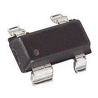
HSMS-2825-TR1 Avago Technologies US Inc., HSMS-2825-TR1 Datasheet - Page 2

HSMS-2825-TR1
Manufacturer Part Number
HSMS-2825-TR1
Description
Diode
Manufacturer
Avago Technologies US Inc.
Specifications of HSMS-2825-TR1
Series Resistance @ If
12ohm
Peak Reflow Compatible (260 C)
No
Reel Quantity
3000
Pin Configuration
Unconnected Pair
Breakdown Voltage Min
15V
Leaded Process Compatible
No
Forward Voltage
340mV
Lead Free Status / RoHS Status
Contains lead / RoHS non-compliant
Available stocks
Company
Part Number
Manufacturer
Quantity
Price
Company:
Part Number:
HSMS-2825-TR1
Manufacturer:
HP
Quantity:
5 321
Company:
Part Number:
HSMS-2825-TR1
Manufacturer:
YEONHO
Quantity:
1 422
Part Number:
HSMS-2825-TR1
Manufacturer:
AGILENT
Quantity:
20 000
Company:
Part Number:
HSMS-2825-TR1G
Manufacturer:
WJ
Quantity:
15 000
Part Number:
HSMS-2825-TR1G
Manufacturer:
AGILENT
Quantity:
20 000
Pin Connections and
Package Marking
1
2
3
Notes:
1.
2.
Electrical Specifications T
Notes:
1. ∆V
2. ∆C
3. Effective Carrier Lifetime (τ) for all these diodes is 100 ps maximum measured with Krakauer method at 5 mA.
4. See section titled “Quad Capacitance.”
5. R
Number Marking Lead
HSMS
Test Conditions
282B
282C
282E
282K
282M
282N
282R
Part
282F
282L
282P
2820
2822
2823
2824
2825
2827
2828
2829
Package marking provides
orientation and identification.
See “Electrical Specifications” for
appropriate package marking.
D
F
TO
= R
for diodes in pairs and quads in 15 mV maximum at 1 mA.
[4]
for diodes in pairs and quads is 0.2 pF maximum.
S
+ 5.2 Ω at 25°C and I
Package
Code
HH
NN
OO
CK
C0
C2
C3
C4
C5
C7
C8
C9
C0
C2
C3
C4
CL
CP
Code Configuration
M
B
C
E
F
K
N
P
R
0
2
3
4
5
7
8
9
L
6
5
4
Single
Series
Common Anode
Common Cathode
Unconnected Pair
Ring Quad
Bridge Quad
Cross-over Quad
Single
Series
Common Anode
Common Cathode
High Isolation
Unconnected Trio
Common Cathode Quad
Common Anode Quad
Bridge Quad
Ring Quad
f
= 5 mA.
Unconnected Pair
[4]
[4]
C
= 25
Absolute Maximum Ratings
Notes:
1.
2.
Symbol Parameter
I
P
T
T
θ
f
Operation in excess of any one of these conditions may result in permanent damage to
the device.
T
contact is made to the circuit board.
jc
IV
j
stg
C
°
= +25°C, where T
C, Single Diode
Breakdown
I
Minimum
R
Forward Current (1 µs Pulse) Amp
Peak Inverse Voltage
Junction Temperature
Storage Temperature
Thermal Resistance
Voltage
V
= 100 µA I
BR
15
(V)
Maximum
Forward
F
C
V
Voltage
= 1 mA
F
is defined to be the temperature at the package pins where
340
(mV)
[2]
[1]
[3]
Maximum
Forward
V
Voltage
I
0.5
F
F
(mA)
(V) @
°C/W
Unit SOT-23/SOT-143 SOT-323/SOT-363
°C
°C
V
10
[1]
T
Maximum
I
Leakage
Reverse
R
C
100
V
2
(nA) @ Capacitance Resistance
R
-65 to 150
= 25°C
(V)
150
500
15
1
1
f = 1 MHz
Maximum
C
V
T
F
1.0
= 0 V
(pF)
[2]
-65 to 150
150
150
15
R
1
Dynamic
I
Typical
F
D
= 5 mA
(Ω Ω Ω Ω Ω )
12
[5]


