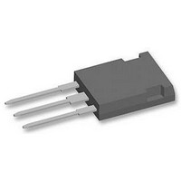
IXGR40N60C2 IXYS SEMICONDUCTOR, IXGR40N60C2 Datasheet

IXGR40N60C2
Manufacturer Part Number
IXGR40N60C2
Description
IGBT, ISOPLUS247
Manufacturer
IXYS SEMICONDUCTOR
Datasheet
1.IXGR40N60C2D1.pdf
(6 pages)
Specifications of IXGR40N60C2
Transistor Type
IGBT
Dc Collector Current
56A
Collector Emitter Voltage Vces
2.7V
Power Dissipation Max
170W
Collector Emitter Voltage V(br)ceo
600V
Operating Temperature Range
-55°C To +150°C
Transistor Case
RoHS Compliant
Power Dissipation Pd
170W
Rohs Compliant
Yes
Available stocks
Company
Part Number
Manufacturer
Quantity
Price
Company:
Part Number:
IXGR40N60C2D1
Manufacturer:
FSC
Quantity:
6 000
HiPerFAST
ISOPLUS247
C2-Class High Speed IGBTs
© 2005 IXYS All rights reserved
(Electrically Isolated Back Surface)
Preliminary Data Sheet
Symbol
BV
V
I
I
V
Symbol
V
V
V
V
I
I
I
I
SSOA
(RBSOA)
P
T
T
T
Maximum Lead temperature for soldering
1.6 mm (0.062 in.) from case for 10 s
V
F
Weight
GES
CM
CES
C25
C110
D110
JM
GE(th)
CE(sat)
GEM
J
stg
C
CES
CGR
GES
C
ISOL
CES
Test Conditions
I
I
V
V
V
I
Test Conditions
T
T
Continuous
Transient
T
T
T
T
V
Clamped inductive load @ V
T
50/60 Hz, RMS, t = 1 minute, I
Mounting force
C
C
C
CE
GE
CE
C
C
C
C
GE
C
J
J
= 25°C to 150°C
= 25°C to 150°C; R
= 25°C
= 110°C
= 110°C (40N60C2D1)
= 25°C, 1 ms
= 15 V, T
= 25°C
= 250μA, V
= 250 μA, V
= V
= 0 V
= 0 V, V
= 30 A, V
CES
TM
GE
TM
VJ
GE
IGBT
= ±20 V
= 125°C, R
GE
= 15 V
CE
= 0 V
= V
GE
GE
= 1 MΩ
G
= 10 Ω
40N60C2
40N60C2/D1
T
T
(T
CE
J
J
ISOL
= 25°C
= 125°C
J
≤ 600 V
= 25°C unless otherwise specified)
< 1 mA
IXGR 40N60C2
IXGR 40N60C2D1
20..120/4.5..25
min.
600
3.0
IXGR_C2
Characteristic Values
-55 ... +150
-55 ... +150
Maximum Ratings
I
CM
typ.
2.2
2.0
600
600
±20
±30
= 80
200
170
150
300
2500
56
26
27
4
max.
±100
IXGR_C2D1
100
5.0
2.7
50
N/lb.
V~
μA
μA
nA
°C
°C
°C
°C
W
V
V
V
V
V
V
V
V
A
A
A
A
A
g
ISOPLUS 247
(IXGR)
Features
Applications
Advantages
G = Gate
E = Emitter
DCB Isolated mounting tab
Meets TO-247AD package Outline
High current handling capability
Latest generation HDMOS
MOS Gate turn-on
- drive simplicity
Uninterruptible power supplies (UPS)
Switched-mode and resonant-mode
power supplies
AC motor speed control
DC servo and robot drives
DC choppers
Easy assembly
High power density
Very fast switching speeds for high
frequency applications
V
I
V
t
C25
fi(typ
CE(SAT)
CES
G
C
E
TM
= 600
= 56
= 2.7
= 32 ns
C = Collector
DS99052C(10/05)
ISOLATED TAB
TM
process
A
V
V
Related parts for IXGR40N60C2
IXGR40N60C2 Summary of contents
Page 1
HiPerFAST IGBT TM ISOPLUS247 TM C2-Class High Speed IGBTs (Electrically Isolated Back Surface) Preliminary Data Sheet Symbol Test Conditions 25°C to 150°C CES 25°C to 150°C; R CGR J V Continuous GES V ...
Page 2
Symbol Test Conditions Pulse test, t ≤ 300 μs, duty cycle ≤ ies ...
Page 3
Fig. 1. Output Characteristics @ 25 Deg 0 Volts C E Fig. 3. Output ...
Page 4
Fig. 7. Transconductance 70 60 º - º º Amperes C Fig. 9. Dependence ...
Page 5
IXYS All rights reserved Fig. 13. Maximum Transient Thermal Resistance 1 0 Pulse Width - milliseconds IXGR 40N60C2 IXGR 40N60C2D1 000 ...
Page 6
=150° =100° =25° Fig. 14. Forward current I versus V F 2.0 1 1.0 I ...


