3RV19011A SIEMENS, 3RV19011A Datasheet - Page 53
3RV19011A
Manufacturer Part Number
3RV19011A
Description
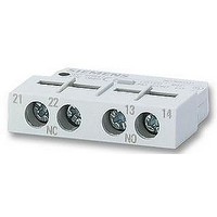
AUXILIARY SWITCH, LATERALLY FIT
Manufacturer
SIEMENS
Datasheet
1.3RV19011A.pdf
(56 pages)
Specifications of 3RV19011A
Approval Bodies
UL, CSA, VDE
Contact Configuration
1 N/C + 1 N/O
No. Of Poles
2
Terminal Type
Screw
Accessory Type
Lateral Auxilary Contact
For Use With
-000 A


3RU11 thermal overload relays with screw connection on the auxiliary current side for stand alone installation
Features and technical specifications:
• Overload and phase failure protection
• Auxiliary contacts 1 NO + 1 NC
• Manual and automatic RESET
1) Size S00 to S3 for screw and snap-on mounting onto TH 35 standard
2) Observe maximum rated operational current of the devices.
3) Standard value for 4-pole standard motors at 50 Hz 400 V AC. The actual
4) Maximum fuse for overload relay, type of coordination 2. For fuse values in
5) For overload relays > 100 A, see 3RB2.
* You can order this quantity or a multiple thereof.
Size S00
Size S0
Size S2
Size S3
mounting rails, size S3 also for TH 75 standard mounting rails.
starting and rated data of the motor to be protected must be considered
when selecting the units.
conjunction with contactors, see Technical Specifications, Short-Circuit
Protection with Fuses/Motor Starter Protectors for Motor Feeders.
Size
Con-
tactor
S00
S0
S2
S3
2)
Rating
for induction
motor,
Rated value
kW
0.04
0.06
0.06
0.09
0.09
0.12
0.18
0.18
0.25
0.37
0.55
0.75
0.75
1.1
1.5
1.5
2.2
3
4
5.5
7.5
7.5
11
11
15
18.5
22
22
30
37
45
45
3)
Set current value
of the inverse-
time delayed
overload trip
A
0.11 ... 0.16
0.14 ... 0.2
0.18 ... 0.25
0.22 ... 0.32
0.28 ... 0.4
0.35 ... 0.5
0.45 ... 0.63
0.55 ... 0.8
0.7 ... 1
0.9 ... 1.25
1.1 ... 1.6
1.4 ... 2
1.8 ... 2.5
2.2 ... 3.2
2.8 ... 4
3.5 ... 5
4.5 ... 6.3
5.5 ... 8
7 ... 10
9 ... 12
11 ... 16
14 ... 20
17 ... 22
20 ... 25
22 ... 32
28 ... 40
36 ... 45
40 ... 50
45 ... 63
57 ... 75
70 ... 90
80 ... 100
5)
Short-circuit
protection
with fuse,
type of coor-
dination 2,
gL/gG
operational
class
A
0.5
1
1
1.6
2
2
2
4
4
4
6
6
10
10
16
20
20
25
35
35
40
50
63
63
80
80
100
100
125
160
160
200
4)
• Switch position indicator
• TEST function
• STOP button
• Integrated, sealable cover
DT Order No.
B
B
B
B
A
A
A
A
}
A
}
}
}
}
}
}
}
}
}
A
}
}
A
}
}
}
A
A
}
A
A
A
3RU11 16-0AB1
3RU11 16-0BB1
3RU11 16-0CB1
3RU11 16-0DB1
3RU11 16-0EB1
3RU11 16-0FB1
3RU11 16-0GB1
3RU11 16-0HB1
3RU11 16-0JB1
3RU11 16-0KB1
3RU11 16-1AB1
3RU11 16-1BB1
3RU11 16-1CB1
3RU11 16-1DB1
3RU11 16-1EB1
3RU11 16-1FB1
3RU11 16-1GB1
3RU11 16-1HB1
3RU11 16-1JB1
3RU11 16-1KB1
3RU11 26-4AB1
3RU11 26-4BB1
3RU11 26-4CB1
3RU11 26-4DB1
3RU11 36-4EB1
3RU11 36-4FB1
3RU11 36-4GB1
3RU11 36-4HB1
3RU11 46-4JB1
3RU11 46-4KB1
3RU11 46-4LB1
3RU11 46-4MB1
3RU1 Thermal Overload Relays
Price
per PU
3RU11 for standard applications
Overload Relays
PU
(UNIT,
SET, M)
Siemens LV 1 · 2006
1
1
1
1
1
1
1
1
1
1
1
1
1
1
1
1
1
1
1
1
1
1
1
1
1
1
1
1
1
1
1
1
PS*
1 unit
1 unit
1 unit
1 unit
1 unit
1 unit
1 unit
1 unit
1 unit
1 unit
1 unit
1 unit
1 unit
1 unit
1 unit
1 unit
1 unit
1 unit
1 unit
1 unit
1 unit
1 unit
1 unit
1 unit
1 unit
1 unit
1 unit
1 unit
1 unit
1 unit
1 unit
1 unit
PG
1)
, CLASS 10
101
101
101
101
101
101
101
101
101
101
101
101
101
101
101
101
101
101
101
101
101
101
101
101
101
101
101
101
101
101
101
101
Weight
per PU
approx.
kg
5/53
0.180
0.180
0.180
0.180
0.180
0.180
0.180
0.180
0.180
0.180
0.180
0.180
0.180
0.180
0.180
0.180
0.180
0.180
0.180
0.180
0.240
0.240
0.240
0.240
0.480
0.480
0.480
0.480
0.810
0.810
0.810
0.810
Related parts for 3RV19011A
Image
Part Number
Description
Manufacturer
Datasheet
Request
R

Part Number:
Description:
Intel 80C32 - Siemens SAB-C501, Nearest Equivalent Replacement
Manufacturer:
Siemens Semiconductor Group
Part Number:
Description:
IGBT MODULE
Manufacturer:
Siemens Semiconductor Group
Datasheet:
Part Number:
Description:
SIMOPAC Module (Power module Single switch N channel Enhancement mode)
Manufacturer:
Siemens Semiconductor Group
Datasheet:
Part Number:
Description:
(BSMxxx) TRANSISTOR
Manufacturer:
Siemens Semiconductor Group
Datasheet:
Part Number:
Description:
SIMOPAC Module (Power module Single switch N channel Enhancement mode)
Manufacturer:
Siemens Semiconductor Group
Datasheet:
Part Number:
Description:
main ratings
Manufacturer:
Siemens Semiconductor Group
Datasheet:
Part Number:
Description:
Manufacturer:
Siemens Semiconductor Group
Datasheet:
Part Number:
Description:
Manufacturer:
Siemens Semiconductor Group
Datasheet:
Part Number:
Description:
Manufacturer:
Siemens Semiconductor Group
Datasheet:
Part Number:
Description:
ICs for Consumer Electronics
Manufacturer:
Siemens Semiconductor Group
Datasheet:
Part Number:
Description:
Video and Sound IF with V & S SCART
Manufacturer:
Siemens Semiconductor Group
Datasheet:
Part Number:
Description:
Manufacturer:
Siemens Semiconductor Group
Datasheet:
Part Number:
Description:
Multistandard Sound IF
Manufacturer:
Siemens Semiconductor Group
Datasheet:
Part Number:
Description:
MULTISTANDARD AM FM SOUND IF IC
Manufacturer:
Siemens Semiconductor Group
Datasheet: