3RV19011A SIEMENS, 3RV19011A Datasheet - Page 44
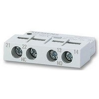
3RV19011A
Manufacturer Part Number
3RV19011A
Description
AUXILIARY SWITCH, LATERALLY FIT
Manufacturer
SIEMENS
Datasheet
1.3RV19011A.pdf
(56 pages)
Specifications of 3RV19011A
Approval Bodies
UL, CSA, VDE
Contact Configuration
1 N/C + 1 N/O
No. Of Poles
2
Terminal Type
Screw
Accessory Type
Lateral Auxilary Contact
For Use With
-000 A


■
3RB2 Solid-State Overload Relays
3RB22, 3RB23 for high-feature applications
Overview
3RB22/3RB23 evaluation module
(1) Green "Ready" LED
(2) Red "Ground fault" LED:
(3) Red "Thermistor" LED:
(4) Red "Overload" LED:
(5) Motor current and trip class adjustment:
(6) Selector switch for manual/automatic RESET:
(7) Test/RESET button:
(8) Connecting terminals (removable terminal block):
(9) 3RB29 85 function expansion module:
3RB29 06 current measuring module
5/44
A continuous green light signals that the device is working correctly.
A continuous red light signals a ground fault.
A continuous red light signals an active thermistor trip.
A continuous red light signals an active overload trip; a flickering red
light signals an imminent trip (overload warning).
Setting the device to the motor current and to the required trip class
dependent on the starting conditions is easy with the two rotary knobs.
With this switch you can choose between manual and automatic
RESET.
Enables testing of all important device components and functions,
plus resetting of the device after a trip when manual RESET is
selected.
The generously sized terminals permit connection of two conductors
with different cross-sections for the auxiliary, control and sensor
circuits. Connection is possible with screw-type terminals and
alternatively with spring-loaded terminals.
Enables more functions to be added, e.g. internal ground fault
detection and/or an analog output with corresponding signals.
Overload Relays
Siemens LV 1 · 2006
The modular, solid-state overload relays with external power
supply type 3RB22 (with monostable auxiliary contacts) and
type 3RB23 (with bistable auxiliary contacts) up to 630 A (up to
820 A possible with a series transformer) have been designed
for inverse-time delayed protection of loads with normal and
heavy starting
temperature rises due to overload, phase unbalance or phase
failure. An overload, phase unbalance or phase failure result in
an increase of the motor current beyond the set motor rated
current. This current rise is detected by means of a current
measuring module and electronically evaluated by a special
evaluation module which is connected to it. The evaluation
electronics sends a signal to the auxiliary contacts. The auxiliary
contacts then switch off the load by means of a contactor. The
break time depends on the ratio between the tripping current
and set current I
tripping characteristic
"tripped" status is signaled by means of a continuous red
"Overload" LED.
The LED indicates imminent tripping of the relay due to overload,
phase unbalance or phase failure by flickering when the limit
current has been violated. This warning can also issued as a
signal through auxiliary contacts.
In addition to the described inverse-time delayed protection of
loads against excessive temperature rises, the 3RB22/3RB23
solid-state overload relays also allow direct temperature moni-
toring of the motor windings (full motor protection) by failsafe
connection of a PTC sensor circuit. With this temperature-depen-
dent protection, the loads can be protected against overheating
caused indirectly by reduced coolant flow, for example, which
cannot be detected by means of the current alone. In the event
of overheating, the devices switch off the contactor, and thus the
load, by means of the auxiliary contacts. The "tripped" status is
signaled by means of a continuously illuminated "Overload" LED.
To also protect the loads against high-resistance short-circuits
due to damage to the insulation, humidity, condensed water,
etc., the 3RB22/3RB23 solid-state overload relays offer the
possibility of internal ground fault monitoring in conjunction with
a function expansion module
Ordering Data;
assembly for Wye-Delta starting). In the event of a ground fault
the 3RB22/3RB23 relays trip instantaneously. The "tripped"
status is signaled by means of a red "Ground Fault" LED.
Signaling through auxiliary contacts is also possible.
After tripping due to overload, phase unbalance, phase failure,
thermistor tripping or ground fault, the relay is reset manually or
automatically after the recovery time has elapsed
Function).
In conjunction with a function expansion module the motor
current measured by the microprocessor can be output in the
form of an analog signal 4 ... 20 mA DC for operating rotary coil
instruments or for feeding into analog inputs of programmable
logic controllers. With an additional AS-Interface analog module
the current values can also be transferred over the
AS-i bus system.
The devices are manufactured in accordance with environmen-
tal guidelines and contain environmentally friendly and reusable
materials.
They comply with all important worldwide standards and
approvals.
(see LV 1 T, Function)
not possible in conjunction with contactor
e
and is stored in the form of a long-term stable
(see LV 1 T, Characteristic
(for details see Selection and
against excessive
Curves). The
(see LV 1 T,
Related parts for 3RV19011A
Image
Part Number
Description
Manufacturer
Datasheet
Request
R

Part Number:
Description:
Intel 80C32 - Siemens SAB-C501, Nearest Equivalent Replacement
Manufacturer:
Siemens Semiconductor Group
Part Number:
Description:
IGBT MODULE
Manufacturer:
Siemens Semiconductor Group
Datasheet:
Part Number:
Description:
SIMOPAC Module (Power module Single switch N channel Enhancement mode)
Manufacturer:
Siemens Semiconductor Group
Datasheet:
Part Number:
Description:
(BSMxxx) TRANSISTOR
Manufacturer:
Siemens Semiconductor Group
Datasheet:
Part Number:
Description:
SIMOPAC Module (Power module Single switch N channel Enhancement mode)
Manufacturer:
Siemens Semiconductor Group
Datasheet:
Part Number:
Description:
main ratings
Manufacturer:
Siemens Semiconductor Group
Datasheet:
Part Number:
Description:
Manufacturer:
Siemens Semiconductor Group
Datasheet:
Part Number:
Description:
Manufacturer:
Siemens Semiconductor Group
Datasheet:
Part Number:
Description:
Manufacturer:
Siemens Semiconductor Group
Datasheet:
Part Number:
Description:
ICs for Consumer Electronics
Manufacturer:
Siemens Semiconductor Group
Datasheet:
Part Number:
Description:
Video and Sound IF with V & S SCART
Manufacturer:
Siemens Semiconductor Group
Datasheet:
Part Number:
Description:
Manufacturer:
Siemens Semiconductor Group
Datasheet:
Part Number:
Description:
Multistandard Sound IF
Manufacturer:
Siemens Semiconductor Group
Datasheet:
Part Number:
Description:
MULTISTANDARD AM FM SOUND IF IC
Manufacturer:
Siemens Semiconductor Group
Datasheet: