ZUP/NC402 TDK Corporation, ZUP/NC402 Datasheet - Page 11
ZUP/NC402
Manufacturer Part Number
ZUP/NC402
Description
LAMBDA PART
Manufacturer
TDK Corporation
Series
ZUPr
Specifications of ZUP/NC402
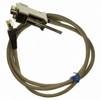
Connector Type
D-Sub 09 pos Male to RS485 8 pos Male
Length
3.28' (1.00m)
Cable Type
Round
Color
White
Shielding
Shielded
Usage
Communication
Lead Free Status / RoHS Status
Lead free / RoHS Compliant
Other names
285-1667


1.1 USER’S MANUAL CONTENT
This user’s manual contains the operating instructions, installation instructions and specifications of
the ZUP series. For information related to operation with GPIB control, refer to Nemic-Lambda GP485
user’s manual.
1.2 INTRODUCTION
1.2.1 General description
1.2.2 Configurations
1.2.3 Control via the serial communication port
The ZUP series are wide range output switching power supplies with laboratory performance. The ZUP
series is power factor corrected and operates from worldwide AC voltage range continuously. Output
voltage and current are continuously displayed and LED indicators show the complete operating status
of the power supply. The front panel controls allow the user to set the output parameters, the protection
levels (over-voltage / under-voltage)and arm the foldback protection to disable the output if the unit
switches from Constant-voltage mode to Constant-current mode.
The ZUP can be configured into a programmable power system of up to 31 DC outputs using the built-in
RS232 or RS485 communication port in the power supply. In a GPIB system the GP485 controller can
control up to 31 ZUP units in a single GPIB address.
The following parameters can be programmed via the serial communication port:
Output connections are made to rear panel bus-bars for models up to 60V and connector for the 80V
and 120V models. Either the positive or negative terminal may be grounded or the output may be
floated. The maximum potential (including the output voltage) that either output terminal is from ground
must not exceed the rated output voltage. Local or remote sense may be used. In remote sense, the
maximum voltage drop on each wire is 0.5V for models up to 60V and 2V for the 80V and 120V models.
1.2.4 Output connections
1.2.5 Analog voltage programming
1.2.6 Parallel operation
Analog inputs are provided at the rear panel for analog voltage programming of output voltage and
current, and On/Off control. Inputs are provided for resistive programming of the output voltage and
current.
Zup units of the same output voltage and current rating can be paralleled in master-slave configuration
with automatic current sharing for power-up purposes.
CHAPTER 1 GENERAL INFORMATION
1. Output voltage setting
2. Output current setting
3. Output On/Off
4. Arming or release of the foldback protection
5. Over-voltage protection setting
6. ‘Soft’ under-voltage limit
7. Output voltage measurement
10. Over-voltage protection setting read
11. Under-voltage limit read
12. Remote/Local Control
8. Output current measurement
9. Power supply start-up mode
(last setting or safe mode)
Related parts for ZUP/NC402
Image
Part Number
Description
Manufacturer
Datasheet
Request
R

Part Number:
Description:
ZUP 200/400W DUAL RACK ASSEMBLY
Manufacturer:
TDK Corporation
Datasheet:
Part Number:
Description:
TDK DC to DC Converters, DC to AC Inverters
Manufacturer:
TDK Corporation
Datasheet:
Part Number:
Description:
TDK DC to DC Converters, DC to AC Inverters
Manufacturer:
TDK Corporation
Datasheet: