SMT15E-12W3V3-TJ Emerson Network Power, SMT15E-12W3V3-TJ Datasheet - Page 21
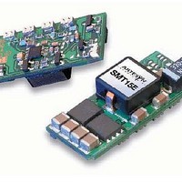
SMT15E-12W3V3-TJ
Manufacturer Part Number
SMT15E-12W3V3-TJ
Description
10-14Vin, 0.8-3.63V@15A, 1.30" X 0.53" X 0.32, 94%Eff, SMT, T&R Packaging, RoHS 6
Manufacturer
Emerson Network Power
Datasheet
1.SMT15E-12W3V3-TJ.pdf
(64 pages)
Specifications of SMT15E-12W3V3-TJ
Product
Non-Isolated / POL
Output Power
55 W
Input Voltage Range
10 V to 14 V
Input Voltage (nominal)
12 V
Number Of Outputs
1
Output Voltage (channel 1)
0.8 V to 3.63 V
Output Current (channel 1)
15 A
Package / Case Size
33.02 mm x 13.46 mm x 8.13 mm
Output Voltage
0.8 V to 3.63 V
Lead Free Status / Rohs Status
Lead free / RoHS Compliant


Ordering Information
Sample below is 1500 W case with 12 V @ 62.5 A; 5 V @ 60 A; 24 V @ 8.5 A; 12 V @ 10 A; 12 V @ 4 A; with no options.
Non-std*
Output Module Voltage/Current
*Note: Increments of current not shown can be achieved by paralleling modules
**Total loading of outputs on dual module not to exceed 144 W.
Voltage
(add currents of each module selected).
2.2 V
3.3 V
5.2 V
5.5 V
6.0 V
8.0 V
Case Size (mm)
4 = 2.5" x 5" x 10"; 750 W-1100 W, 5 Slots
8 = 2.5" x 7" x 10"; 1000 W-1200 W, 6 Slots
1 = 2.5" x 8" x 11"; 1200 W-1500 W, 7 Slots
*Note: Add "E" after iMP4 to denote IEC
input option. e.g. iMP4E
(Not available on iMP8 or iMP1)
10 V
11 V
12 V
14 V
15 V
18 V
20 V
24 V
28 V
30 V
33 V
36 V
42 V
48 V
54 V
60 V
2 V
3 V
5 V
(63.5 x 127 x 254)
(63.5 x 177.8 x 254)
(63.5 x 203.2 x 279.4)
Voltage
Code
W
M
O
Q
A
C
D
G
H
K
N
R
U
V
X
Y
Z
B
E
F
L
P
S
T
I
J
iMP1*
Case Size
10.5 A
Single Output Module Code
8.5 A
6.7 A
6.5 A
6.2 A
5.8 A
4.2 A
4.0 A
3.7 A
3.5 A
35 A
35 A
35 A
35 A
35 A
35 A
34 A
23 A
20 A
18 A
17 A
17 A
14 A
14 A
11 A
1
Special Voltage - Consult Factory for specifications
12.8 A
7.5 A
7.5 A
6.0 A
6.0 A
60 A
60 A
60 A
60 A
60 A
60 A
58 A
42 A
36 A
32 A
31 A
30 A
21 A
20 A
19 A
18 A
15 A
12 A
11 A
10 A
2
62.5 A
53.5 A
41.6 A
37.5 A
31.3 A
26.8 A
22.7 A
20.8 A
17.9 A
15.6 A
13.9 A
12.5 A
For complete product specifications, technical reference notes and available product options, go to www.powerconversion.com.
150 A
150 A
150 A
150 A
150 A
150 A
137 A
80 A
80 A
75 A
68 A
50 A
25 A
3
- 3L0 - 2E2 - 1Q1 - 4LL0 -
10 A
10 A
10 A
10 A
10 A
10 A
10 A
10 A
10 A
10 A
10 A
10 A
Module Codes
Module/voltage/option codes
Module codes:
(None) = 36 W triple O/P (1 slot)
1 = 210 W single O/P (1 slot)
2 = 360 W single O/P (2 slot)
3 = 750 W single O/P (3 slot)
4 = 144 W dual O/P (1 slot)
5 - 9 = future
Dual Output**
Voltage Codes:
See Output Module Voltage/Current
table above
Option Codes:
0 = Standard
1 = Module enable
2 = Constant current
3 = 1 & 2 combined
4 = Set for use in standard
5 - 4 = Future
9 A
8 A
4 A
3 A
V1
—
—
—
—
—
—
—
—
—
Module/Voltage/Option Codes
(non-intelligent case)
Second - Voltage Code
Third - Option Code
First - Module Code
10 A
10 A
10 A
10 A
10 A
10 A
10 A
10 A
4 A
4 A
4 A
4 A
4 A
4 A
2 A
2 A
V2
—
—
—
—
—
—
—
—
—
Adjustment
1.8-6.1
5.4-13.2
12.6-22.0
21.6-39.6
37.8-60.0
Ranges
I
2
C
Ordering Note:
1. The cases and modules of both MP and iMP series can be inter-
2. USB to I2C module order code 73-769-001
Case Option Codes
First digit
0 - 9 = parallel code
(See Parallel Codes table above)
Second digit
0 = No options
1 = Reverse air
3 = Global enable
4 = Fan off w/inhibit
5 = Opt 1 + Opt 3
6 = Opt 1 + Opt 4
7 = Opt 3 + Opt 4
8 = Opt 1 +3 +4
9 = Future
changed to allow more flexibility. If intelligent modules are used
with non-intelligent cases, a numeric code “4” is placed at the end
of the module code (ex. 4LL0 becomes 4LL4).
Case Option Codes
00
Parallel Codes
Intelligent Medium Power
7
-
Software code
used for configu-
ration change. “A”
is standard
Software Code
6
5 4
A
3
2
-
1
Factory assembled
for hardware of
firmware mods.
Hardware Code
iMP4
available slots
iMP8
iMP1
0 = no parallel
1 = 1 & 2
2 = 2 & 3
3 = 3 & 4
4 = 4 & 5
5 = 3 & 4 & 5
6 = 5 & 6
7 = 4 & 5 & 6
8 = 6 & 7
9 = 3 & 4, 6 & 7
available slots
available slots
###
21
Related parts for SMT15E-12W3V3-TJ
Image
Part Number
Description
Manufacturer
Datasheet
Request
R

Part Number:
Description:
CONV DC/DC 12VIN 3.3VOUT 15A SMD
Manufacturer:
Emerson Network Power
Datasheet:

Part Number:
Description:
CONV DC/DC 5VIN 3.3V OUT 15A SMD
Manufacturer:
Emerson Network Power
Datasheet:

Part Number:
Description:
CONV DC/DC 5VIN 2.5V OUT 15A SMD
Manufacturer:
Emerson Network Power
Datasheet:

Part Number:
Description:
CONV DC/DC 5VIN 3.3VOUT 15A SMD
Manufacturer:
Emerson Network Power
Datasheet:

Part Number:
Description:
CONV DC/DC 5VIN 3.3V OUT 15A SMD
Manufacturer:
Emerson Network Power
Datasheet:

Part Number:
Description:
CONV DC/DC 5VIN 3.3VOUT 15A SMD
Manufacturer:
Emerson Network Power
Datasheet:

Part Number:
Description:
CONV DC/DC 12VIN 3.3VOUT 15A SMD
Manufacturer:
Emerson Network Power
Datasheet:

Part Number:
Description:
Smt15e Series | 15 A Dc-dc E Class Non-isolated Dc-dc Converters
Manufacturer:
Astec Powe
Datasheet:

Part Number:
Description:
3.0-5.5Vin, 0.8-3.63V@15A, 1.30" X 0.53" X 0.32, 95%Eff, SMT, T&R Packaging, RoHS 6
Manufacturer:
Emerson Network Power
Datasheet:

Part Number:
Description:
DC/DC CONVERTERS 50W Non-isolated DC/DC Converters
Manufacturer:
Artesyn Technologies, Inc.
Part Number:
Description:
AC/DC Front end 12Vo 36A 12Vsb Standard Airflow
Manufacturer:
Emerson Network Power

Part Number:
Description:
POWER SUPPLY DIN 24VDC 10A
Manufacturer:
Emerson Network Power
Datasheet:

Part Number:
Description:
POWER SUPPLY SGL 48VOUT 40W 3X5"
Manufacturer:
Emerson Network Power
Datasheet:

Part Number:
Description:
POWER SUP MED&ITE 48V 45W 2"X4"
Manufacturer:
Emerson Network Power
Datasheet:

Part Number:
Description:
POWER SUPPLY 60W 12V OUT
Manufacturer:
Emerson Network Power
Datasheet: