DMS-EB-AC/DC-C Murata Power Solutions Inc, DMS-EB-AC/DC-C Datasheet - Page 3
DMS-EB-AC/DC-C
Manufacturer Part Number
DMS-EB-AC/DC-C
Description
DMS-30 AC-Power Appl. Board
Manufacturer
Murata Power Solutions Inc
Datasheet
1.DMS-EB-ACDC-C.pdf
(4 pages)
Specifications of DMS-EB-AC/DC-C
Lead Free Status / RoHS Status
Lead free / RoHS Compliant


1. Decimal Point Placement: DATEL ships the DMS-EB-AC/DC with
2. Span (Gain) and Zero (Offset) Adjustments (See Figure 3): Loca-
Using Potentiometer R4 for Span Adjustment (DMS-30PC and DMS-
all decimal point solder gaps (SG1, SG2, SG3 and SG4) open. To
enable a specific decimal point, close its respective solder gap with
solder. When reassigning decimal places for subsequent applications,
remember to open any previously closed solder gaps.
Close SG1 for 1.999 (DP1)
Close SG2 for 19.99 (DP2)
Close SG3 for 199.9 (DP3)
Close SG4 for 1999.9 (DP4 on DMS-40LCD)
tions are included on the DMS-EB-AC/DC to add user-supplied potenti-
ometers R4 and R5. Recommended values for these two components
are as follows: R4: 2KΩ, 10-20-turns; R5: 50KΩ, 10-20 turns. Vishay's
T93YA series potentiometers are suitable for this application. Make
sure to use only RoHS-compliant components and solders when mak-
ing modifications to DMS-EB-AC/DC.
Once installed, these components permit the span and zero adjust-
ments described in the following sections. R4 provides span adjust,
while R5 applies and offset voltage to (-) IN LO (J1, pin 2).
30LCD Meters Only)
1. For DMS-30-1, -2, and -3 models (+/-2V, +/-20V, +/-200V ranges):
2. For DMS-30-0 models (+/-200mV ranges): Span adjustment re-
Configuring the DMS-EB-AC/DC for span adjustment is simply a
matter of installing potentiometer R4, opening SG13, and then clos-
ing SG8, SG11, and SG12.
quires that you open SG8, SG11 (if closed) and SG13 and then close
SG7, SG and SG12. Then install R4.
Adjust span as desired. DMS-30-1, -2, and -3 span adjustment
range is typically +10% and –5%. The DMS-30-0 has a much wider
span adjust, however, it should be limited to ±10% for optimum
accuracy and stability.
SG13
DP4
SG7
SG8
12
SG12
SG4
www.murata-ps.com
SG14
R3
SG11
SG10
SG6
SG9
TB1
HI(+)
1
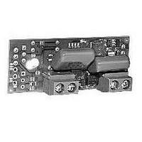
Figure 2. DMS-EB-AC/DC Board
LO(–)
2
APPLICATIONS
Accessory Board for DMS-30PC/LCD Panel Meters
Using Potentiometer R5 to Apply a Positive Offset to Pin 12 (-) IN LO
3. Measuring Input Voltages Greater than 1.999Vdc (Use DMS-30-
CAUTION: Do not apply inputs greater than +/-250Vdc.
Where:
0 or DMS-30-1 Only): If possible, the resistors used for R1 and R2
should be ±1% metal-film types with TCR’s less than or equal to
100ppm/°C. More information on selecting 1% resistors can be found
in Application Note 14.
1. Open SG14 and close SG6.
2. Install 50K potentiometer R5.
1. Open SG10. For applications in which input voltages exceed
2. Configure the DMS-EB-AC/DC for span adjust using the procedure
3. Calculate values for R1 and R2 as follows:
Potentiometer R5 applies a stable, positive dc-offset voltage to
the meter’s IN LO terminal. This offset voltage has a range of 0 to
+1.2Vdc, measured with respect to TB1 terminal 2 (LO). It can be
used to null (or cancel) the effects of an input whose zero level is
not exactly zero volts. For example, adjusting R5 allows the display
to read “000” with an input whose lowest level is slightly above
zero volts. Please note, R5 cannot compensate for inputs whose
zero level is negative (i.e., if TB1 HI is more negative than TB1 LO).
±100Vdc, also cut the 2 adjoining traces.
previously outlined.
A typical value for R1 is 1MΩ. The sum of R1 + R2 should be
between 50kΩ and 10MΩ.
R2 = (FSI x R1) / ( |Vin| - FSI)
FSI = The attenuated voltage between the meter’s (–) IN LO and
(+) IN HI pins (pins 12 and 11, respectively) needed to achieve the
desired display readings
Vin = Input signal at TB1 terminals 1 and 2, disregarding polarity
AC LO
Technical enquiries email: sales@murata-ps.com, tel:
1
AC HI
TB2
2
1
DMS-EB-AC/DC
100-264Vac Power Supply
SG3 (DP3)
SG2 (DP2)
SG1 (DP1)
MPM_DMS-EB-AC/DC.B01 Page 3 of 4
+1 508 339 3000
Related parts for DMS-EB-AC/DC-C
Image
Part Number
Description
Manufacturer
Datasheet
Request
R


Part Number:
Description:
DMS-30 Temp. Appl. Board Cel
Manufacturer:
Murata Power Solutions Inc
Datasheet:
Part Number:
Description:
DMS-30 Temp. Appl. Board Farn
Manufacturer:
Murata Power Solutions Inc
Datasheet:

Part Number:
Description:
Ac-to-rms Converter Application Board For Dms-30pc/lcd Meters
Manufacturer:
Murata Manufacturing Co., Ltd
Datasheet:
Part Number:
Description:
4-20ma Current Loop Application Board For Dms-30lcd Meters
Manufacturer:
Murata Manufacturing Co., Ltd
Datasheet:
Part Number:
Description:
High-accuracy Temperature Sensor Boards Dms-30pc/lcd-0 Meters
Manufacturer:
Murata Manufacturing Co., Ltd
Datasheet:
Part Number:
Description:
Dc/dc Converter And Isolation Board For Dms-30pc/lcd Meters
Manufacturer:
Murata Manufacturing Co., Ltd
Datasheet:
Part Number:
Description:
100-264vac Power Supply Accessory Board For Dms-30pc/lcd Panel Meters
Manufacturer:
Murata Manufacturing Co., Ltd
Datasheet:

Part Number:
Description:
Application Board
Manufacturer:
Murata Power Solutions Inc
Datasheet:

Part Number:
Description:
DC/DC CONVERTER FOR DMS30PC METERS
Manufacturer:
Murata Power Solutions Inc
Datasheet:

Part Number:
Description:
DATEL PANEL METERS
Manufacturer:
Murata Power Solutions Inc
Datasheet:

Part Number:
Description:
DMS-EB Blank PC-Board DMS-30
Manufacturer:
Murata Power Solutions Inc
Datasheet:

Part Number:
Description:
POWER OVER ETHERNET MODULE
Manufacturer:
Murata Power Solutions Inc
Datasheet:

Part Number:
Description:
POWER OVER ETHERNET MODULE
Manufacturer:
Murata Power Solutions Inc
Datasheet:

Part Number:
Description:
POWER OVER ETHERNET MODULE
Manufacturer:
Murata Power Solutions Inc
Datasheet: