NLP110-9617J Emerson Network Power, NLP110-9617J Datasheet - Page 3
NLP110-9617J
Manufacturer Part Number
NLP110-9617J
Description
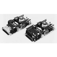
POWER SUPPLY, SWITCH MODE, 48V
Manufacturer
Emerson Network Power
Datasheet
1.NLP110-9617.pdf
(4 pages)
Specifications of NLP110-9617J
Power Supply Type
Open Frame
Power Supply Output Type
Fixed
No. Of Outputs
1
Output Voltage
48V
Output Current
1.6A
Power Rating
110W
Input Voltage
90V AC To 264V AC
Length
165.1mm
Width
76.2mm
Product
Switching
Lead Free Status / RoHS Status
Lead free / RoHS Compliant
Lead Free Status / RoHS Status
Lead free / RoHS Compliant
Available stocks
Company
Part Number
Manufacturer
Quantity
Price
Company:

Part Number:
NLP110-9617J
Manufacturer:
artesyn
Quantity:
1 000


Notes
1 Free air convection.
2 150 LFM forced air cooling from L4 side.
3 300 LFM forced air cooling from L4 side.
4 Peak output current lasting less than 30 seconds with duty cycle less than
5 Figure is peak-to-peak for convection power rating. Output noise
6 Minimum load required for correct start-up and operation on single outputs
Ordering Information
+3.3 V (A)
+3.3 V (B)
+2.5 V (B)
+3.3 V (B)
+12 V (A)
+12 V (A)
+5 V (A)
+5 V (B)
Voltage
Output
Multiple output units: maximum continuous output power not to exceed
80 W.
For -9693J; I
For -9694J; I
For -9695J; I
For -9608J; I
Single output units: maximum continuous output power not to exceed; 75 W
on -9905J; 76.8 W on -9912J,-9924J, and -9917J.
Multiple output units: maximum continuous output power not to exceed 105
W.
For -9693J; I
For -9694J; I
For -9695J; I
For -9608J; I
Single output units: maximum continuous output power not to exceed 110 W
for all models.
Multiple output units: maximum continuous output power not to exceed 110
W.
For -9693J; I
For -9694J; I
For -9695J; I
For -9608J; I
Single output units: maximum continuous output power not to exceed 110 W
for all models.
5%. During peak loading, output voltage may exceed total regulation limits.
measurements are made across a 20 MHz bandwidth using a 6’ twisted pair,
terminated with a 10 µF electrolytic capacitor and a 0.1 µF ceramic capacitor.
and on main output of multiple versions. Failure to observe minimum
load on main output will not allow the supply to start-up correctly. Some
electronic test loads have a large delay time before they start drawing
current even though the voltage from the supply is present. During this time
delay, there is no load on the output and as a result, the supply cannot start-
up properly and maintain its correct output voltage. In these instances, a
dummy resistive load across the output may be necessary to load the output
of the supply until the test load can function correctly and draw the intended
minimum load. Minimum load required on auxiliary outputs to maintain
regulation.
+12 V
+48 V
+24 V
+12 V
+12 V
-12 V
-12 V
+5 V
3.3 V
3.3 V
3.3 V
5.0 V
3.3 V
3.3 V
3.3 V
5.0 V
3.3 V
3.3 V
3.3 V
5.0 V
Min
0.5 A
0.3 A
0.2 A
0.5 A
0.2 A
0.5 A
0.1 A
0.2 A
0.5 A
0.2 A
0.2 A
0 A
0 A
0 A
0 A
0 A
= 13 A max.; I
= 13 A max.; I
= 13 A max.; I
= 13 A max.; I
= 16 A max.; I
= 16 A max.; I
= 16 A max.; I
= 16 A max.; I
= 20 A max.; I
= 20 A max.; I
= 20 A max.; I
= 20 A max.; I
(6)
Max
0.65 A
0.65 A
0.65 A
0.65 A
6.4 A
1.6 A
3.2 A
6.5 A
6.5 A
15 A
13 A
13 A
13 A
13 A
13 A
13 A
(1)
5.0 V
2.5 V
12 V
12 V
5.0 V
2.5 V
12 V
12 V
5.0 V
2.5 V
12 V
12 V
150 LFM
= 6.5 A max.; I
= 6.5 A max.; I
= 8.5 A max.; I
= 8.5 A max.; I
= 8.5 A max.; I
= 8.5 A max.; I
= 13 A max.; I
= 13 A max.; I
= 16 A max.; I
= 16 A max.; I
= 18 A max.; I
= 20 A max.; I
9.2 A
2.3 A
4.6 A
8.5 A
8.5 A
22 A
16 A
16 A
16 A
16 A
16 A
16 A
1 A
1 A
1 A
1 A
(2)
300 LFM
3.3 V
3.3 V
3.3 V
3.3 V
3.3 V
3.3 V
3.3 V
5.0 V
3.3 V
5.0 V
3.3 V
5.0 V
9.2 A
2.3 A
4.6 A
8.5 A
8.5 A
22 A
18 A
20 A
20 A
20 A
20 A
18 A
1 A
1 A
1 A
1 A
+ I
+ I
+ I
+ I
+ I
+ I
+ I
+ I
+ I
+ I
+ I
+ I
5.0 V
2.5 V
5.0 V
2.5 V
5.0 V
2.5 V
12 V
12 V
12 V
12 V
12 V
12 V
(3)
² 16 A.
² 16 A.
² 20 A.
² 20 A.
² 22 A.
² 22 A.
² 16 A.
² 16 A
² 20 A.
² 20 A
² 22 A.
² 22 A
Peak
11.5 A
2.5 A
6.0 A
22 A
18 A
20 A
22 A
22 A
10 A
22 A
10 A
22 A
1 A
1 A
1 A
1 A
(4)
Ripple
120 mV
240 mV
240 mV
120 mV
120 mV
120 mV
120 mV
120 mV
120 mV
50 mV
50 mV
50 mV
50 mV
50 mV
50 mV
50 mV
7 For models NLP110-9608J and NLP110-9695J, the 12 V output is floating.
8 Three orthogonal axes, random vibration 10 minutes for each axes, 2.4 G rms
9 For optimum reliability, no part of the heatsink should exceed 110 ˚C, and no
10 CAUTION: Allow a minimum of 1 second after disconnecting line power
11 This product is only for inclusion by professional installers within other
12 The EMI specifications reference measurements made with the power supply
13 All models require a minimum mounting stand-off of 6.35 mm (0.25 inches)
14 The ‘J’ suffix indicates that these parts are Pb-free (RoHS 6/6) compliant.
15 NOTICE: Some models do not support all options. Please contact your local
(5)
For -12 V output, pin 11 on J2 has to be connected to Return making pin 12
the -12 V output
5 Hz to 500 Hz.
semiconductor case temperature should exceed 120 ˚C.
when making thermal measurements.
equipment and must not be operated as a stand alone product.
mounted on a grounded metal sheet extending 1 inch beyond each edge,
using an unshielded cable. No external filtering required during conducted
emissions testing but some applications may require additional filtering
to achieve system compliance. A line choke, (ac input cords looped twice
through an EMI suppression toroid) was used during radiated emissions
testing. Considerable radiated testing in 1U six-sided boxes has shown that
units can meet level B in typical systems. Application support is available
from the factory to assist with EMI compliance.
in the end use product.
Emerson Network Power representative or use the on-line model number
search tool at http://www.PowerConversion.com/products.
Regulation
± 2.0%
± 2.0%
± 2.0%
± 2.0%
± 2.0%
± 2.0%
± 5.0%
± 2.0%
± 2.0%
± 5.0%
± 2.0%
± 2.0%
± 5.0%
± 2.0%
± 2.0%
± 5.0%
Total
Model Numbers
NLP110-9605J
NLP110-9612J
NLP110-9617J
NLP110-9624J
NLP110-9693J
NLP110-9694J
NLP110-9695J
NLP110-9608J
(7, 14, 15)
Embedded Power for
Business-Critical Continuity
Rev. 02.10.09_152
NLP110 Series
of 4
Related parts for NLP110-9617J
Image
Part Number
Description
Manufacturer
Datasheet
Request
R

Part Number:
Description:
POWER SUPPLY 48V SINGLE OUT 75W
Manufacturer:
Emerson Network Power
Datasheet:

Part Number:
Description:
POWER SUPPLY 12,5,-12 80W
Manufacturer:
Emerson Network Power
Datasheet:

Part Number:
Description:
POWER SUPPLY 5V SINGLE OUT 75W
Manufacturer:
Emerson Network Power
Datasheet:

Part Number:
Description:
POWER SUPPLY 12V SINGLE OUT 75W
Manufacturer:
Emerson Network Power
Datasheet:

Part Number:
Description:
POWER SUPPLY 24V SINGLE OUT 75W
Manufacturer:
Emerson Network Power
Datasheet:

Part Number:
Description:
POWER SUPPLY 5V,3.3V,12V OUT 80W
Manufacturer:
Emerson Network Power
Datasheet:

Part Number:
Description:
POWER SUPPLY 3.3V,2.5V 12V, 80W
Manufacturer:
Emerson Network Power
Datasheet:

Part Number:
Description:
POWER SUPPLY 12V,3.3V,-12V 80W
Manufacturer:
Emerson Network Power
Datasheet:

Part Number:
Description:
POWER SUPPLY, SWITCH MODE, 5V
Manufacturer:
Emerson Network Power
Datasheet:
Part Number:
Description:
POWER SUPPLY, SWITCH MODE, 24V
Manufacturer:
Emerson Network Power
Datasheet:

Part Number:
Description:
AC/DC Front end 12Vo 36A 12Vsb Standard Airflow
Manufacturer:
Emerson Network Power

Part Number:
Description:
POWER SUPPLY DIN 24VDC 10A
Manufacturer:
Emerson Network Power
Datasheet:

Part Number:
Description:
POWER SUPPLY SGL 48VOUT 40W 3X5"
Manufacturer:
Emerson Network Power
Datasheet:

Part Number:
Description:
POWER SUP MED&ITE 48V 45W 2"X4"
Manufacturer:
Emerson Network Power
Datasheet:

Part Number:
Description:
POWER SUPPLY 60W 12V OUT
Manufacturer:
Emerson Network Power
Datasheet: