LSN2-T/10-D12G-C Murata Power Solutions Inc, LSN2-T/10-D12G-C Datasheet - Page 3
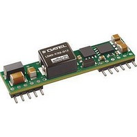
LSN2-T/10-D12G-C
Manufacturer Part Number
LSN2-T/10-D12G-C
Description
DC/DC Converter
Manufacturer
Murata Power Solutions Inc
Series
LSN2r
Datasheet
1.LSN2-T10-D12G-C.pdf
(15 pages)
Specifications of LSN2-T/10-D12G-C
No. Of Outputs
1
Input Voltage
8.3V To 14V
Power Rating
50W
Output Current
10A
Approval Bodies
UL, CSA
Supply Voltage
14VDC
Dc / Dc Converter Case Style
SIP
Dc/dc Converter Mounting
Through Hole
Product
Non-Isolated / POL
Output Power
50 W
Input Voltage Range
8.3 V to 14 V
Input Voltage (nominal)
12 V
Number Of Outputs
1
Output Voltage (channel 1)
0.75 V to 5 V
Output Current (channel 1)
10 A
Package / Case Size
SIP
Output Type
Low Voltage Selectable
Output Voltage
0.75 V to 5 V
Lead Free Status / RoHS Status
Lead free / RoHS Compliant


Performance/Functional Specifi cations
Input Voltage Range
Isolation
Start-Up Threshold
Undervoltage Shutdown
Overvoltage Shutdown
Refl ected (Back) Ripple Current
Internal Input Filter Type
Reverse Polarity Protection
Input Current:
Remote On/Off Control: (5)
Voltage Output Range
Minimum Loading
Accuracy (50% load)
Voltage Adjustment Range (13)
Temperature Coeffi cient
Ripple/Noise (20 MHz bandwidth)
Line/Load Regulation (See Tech Notes) See Ordering Guide and
Effi ciency
Maximum Capacitive Loading: (15)
Full Load Conditions
Inrush Transient
Shutdown Mode (Off, UV, OT)
Output Short Circuit
No Load
Low Line (V
LSN2-T/6 models:
Cap-ESR = 0.001 to 0.01:
Cap-ESR >0.01:
LSN2-T/10 and -T/16 models:
Cap-ESR = 0.001 to 0.01:
Cap-ESR >0.01:
W3 Models
12V Models
W3 Models
12V Models
Positive Logic (no model suffi x)
Negative Logic (“N” model suffi x)
Current
W3 models
12V models
LSN2-T/6-W3
LSN2-T/6-D12
LSN2-T/10-W3
LSN2-T/10-D12
LSN2-T/16-W3
LSN2-T/16-D12
IN
= V
MIN
)
(2)
OUTPUT
INPUT
See Ordering Guide
Not isolated, input and output commons
are internally connected
2.2 Volts
8 Volts
2.0 Volts
7.5 Volts
None
10-70mAp-p (model dependent)
Capacitive
See fuse information
OFF = ground pin to +0.8V max.
ON = open pin or +2.5V min. to +V
ON = open pin to +0.3V max.
OFF = +2.5V min. to +V
1mA max.
See Ordering Guide
No minimum load
±2% of V
See Ordering Guide
±0.02% of V
See Ordering Guide and
See Ordering Guide
See Ordering Guide
0.1A
5mA
60mA
50mA
100mA
5.54 Amps
3.85 Amps
9.14 Amps
6.31 Amps
14.63 Amps
10.2 Amps
3000μF
5000μF
5000μF
10,000μF
2
sec
NOM
OUT
range per °C
(1)
IN
(8)
(10)
max.
www.murata-ps.com
IN
max.
Current Limit Inception: (98% of V
Short Circuit Mode (6)
Short Circuit Duration
Prebias Startup (16)
Sequencing
Remote Sense to V
Power Good Output (14)
Dynamic Load Response
Start-Up Time
Switching Frequency
Calculated MTBF (4)
Operating Temperature Range (Ambient)
Operating PC Board Temperature
Storage Temperature Range
Thermal Protection/Shutdown
Relative Humidity
Outline Dimensions
Removable Heat Shield
Pin Material
Weight
Electromagnetic Interference
Safety
Flammability Rating
LSN2-T/6 models
LSN2-T/10 models
LSN2-T/16 models
Short Circuit Current Output
Protection Method (17)
Slew Rate
Startup delay until sequence start
Tracking accuracy, rising input
Tracking accuracy, falling input
Sequence pin input impedance
(“G” suffi x)
Power_Good Confi guration
(50-100-50% load step, di/dt = 20A/msec)
LSN2-T/6 models
LSN2-T/10 and -T/16 models
No derating, natural convection
With derating
(conducted and radiated)
OUT
DYNAMIC CHARACTERISTICS
ENVIRONMENTAL
Selectable-Output DC/DC Converters
OUT
PHYSICAL
25 Jun 2010
Non-isolated, DOSA-SIP, 6/10/16A
)
11-13 Amps (cold startup)
11 Amps (after warm up)
18.75 Amps (cold startup)
16.75 Amps (after warm up)
24 Amps (cold startup)
21 Amps (after warm up)
600mA
Hiccup autorecovery on overload removal
Continuous, no damage (output shorted
to ground)
Converter will start up if the external
output voltage is less than V
2V max. per millisecond
10 milliseconds
V
V
400k: to 1M:
0.5V max. (7)
TRUE (OK) = open drain
FALSE (not OK) = Signal Ground to 0.4V
MOSFET to ground with external user
pullup, 10mA max. sink
25μsec to ±2% of fi nal value
4-7msec for V
(V
315kHz
230kHz
TBC Hours
–40 to +63°C, vertical mount, 2.5V
See Derating Curves
–40 to +100°C max. (12)
–55 to +125°C
+115°C
To +85% / +85°C
See Mechanical Specifi cations
Nylon 46
Tin-plated copper alloy
0.28 ounces (7.8 grams)
FCC part 15, class B, EN55022
(may need external fi lter)
UL/cUL 60950-1, CSA-C22.2 No.234
IEC/EN 60950-1
UL94V-0
OUT
OUT
IN
on to V
= ±100mV of Sequence In
= ±200mV of Sequence In
LSN2 Series
email: sales@murata-ps.com
OUT
MDC_LSN2.B07Δ
OUT
regulated or On/Off to V
= nominal
NOM
Page 3 of 15
OUT
OUT
(9)
)
Related parts for LSN2-T/10-D12G-C
Image
Part Number
Description
Manufacturer
Datasheet
Request
R

Part Number:
Description:
CONV DC/DC 33W 10A .75-3.3V SIP
Manufacturer:
Murata Power Solutions Inc
Datasheet:

Part Number:
Description:
CONV DC/DC 50W 10A 0.75-5V SIP
Manufacturer:
Murata Power Solutions Inc
Datasheet:

Part Number:
Description:
CONV DC/DC 33W 10A .75-3.3V SIP
Manufacturer:
Murata Power Solutions Inc
Datasheet:

Part Number:
Description:
CONV DC/DC 50W 10A 0.75-5V SIP
Manufacturer:
Murata Power Solutions Inc
Datasheet:

Part Number:
Description:
DC/DC Converter
Manufacturer:
Murata Power Solutions Inc
Datasheet:
Part Number:
Description:
DC/DC Converter
Manufacturer:
Murata Power Solutions Inc
Datasheet:
Part Number:
Description:
DC/DC Converter
Manufacturer:
Murata Power Solutions Inc
Datasheet:

Part Number:
Description:
DC/DC Converters & Regulators 12Vin 0.8-5Vout 30A 150W Power Good Out
Manufacturer:
Murata Power Solutions Inc
Datasheet:

Part Number:
Description:
DC/DC Converters & Regulators 12Vin 0.8-5Vout 22A 112W NonIso DOSA-SIP
Manufacturer:
Murata Power Solutions Inc
Datasheet:
Part Number:
Description:
DC/DC Converters & Regulators 12Vin 0.8-5Vout 22A 112W Neg polarity
Manufacturer:
Murata Power Solutions Inc
Datasheet:

Part Number:
Description:
Transformers 5Vin 5Vout 200mA 4000Vdc 1:1.33 turn
Manufacturer:
Murata Power Solutions Inc
Datasheet:

Part Number:
Description:
POWER SUPPLY
Manufacturer:
Murata Power Solutions Inc
Datasheet:

Part Number:
Description:
DPM LED MINI 2VDC 3.5DIG LP RED
Manufacturer:
Murata Power Solutions Inc
Datasheet:

Part Number:
Description:
CONV DC/DC 1W 5VIN 5VOUT SIP SGL
Manufacturer:
Murata Power Solutions Inc
Datasheet:

Part Number:
Description:
CONV DC/DC 1W 5VIN 3.3V SIP SGL
Manufacturer:
Murata Power Solutions Inc
Datasheet: