AEO04B48N-6L Emerson Network Power, AEO04B48N-6L Datasheet
AEO04B48N-6L
Specifications of AEO04B48N-6L


Related parts for AEO04B48N-6L


AEO04B48N-6L Summary of contents
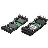
Page 1
AEO/ALO Single Output 8 The AEO_ALO04/12/20/25x48 series is Astec’s Low Current 8 voltage range of 36V to 75V, the series provides 7 configured outputs starting from 1.2V all the way up to 12V. It delivers up to 25A max current ...
Page 2
Electrical Specifications ABSOLUTE MAXIMUM RATINGS Stresses in excess of the absolute maximum ratings can cause permanent damage to the converter. Functional operation of the device is converter is not implied at these or any other conditions in excess of those ...
Page 3
Electrical Specifications (continued) INPUT SPECIFICATIONS Parameter 3 Input Ripple Current Inrush Current OUTPUT SPECIFICATIONS Parameter Output Voltage Set point IN, MIN IN, MAX MAX Output Regulation ...
Page 4
Electrical Specifications (continued) OUTPUT SPECIFICATIONS Parameter Output Current-limit Inception 25º NOM IN, NOM Non-latching / auto-recovery External Load Capacitance resistive load O ...
Page 5
Electrical Specifications (continued) OUTPUT SPECIFICATIONS Parameter Dynamic Response di/dt = 0.1 A/µs Peak Deviation ∆I = 50 Settling Time Vref = Vo nom Peak Deviation ∆I = 50 Settling Time ...
Page 6
Electrical Specifications (continued) BATTERY Measure input reflected-ripple current with a simulated source inductance (Ltest) of 12uH. Capacitor Cs offsets possible battery impedance. Measure current as shown above. Figure 1. Input Reflected Ripple Current Measurement Setup. Vo(+) Vo(-) Use a 0.1µF ...
Page 7
Basic Operation and Features INPUT UNDER VOLTAGE LOCKOUT To prevent any instability to the converter, which may affect the end system, the converter have been designed to turn-on once the voltage range 36VDC. Likewise, ...
Page 8
Basic Operation and Features (continued) OUTPUT ENABLE The converter comes with an Enable pin (PIN 2), which is primarily used to turn ON/OFF the converter. Both a Positive (no “N” suffix required) and a Negative (suffix “N” required) Enable Logic ...
Page 9
Performance Curves 12V @ 4A Efficiency vs. Output Current, T 95% 90% 85% 80% 75% 70% 65% 60% 55 Output Current [A] Figure 5. Efficiency vs. Load Current 25°C (ambient temperature). A Figure 7. ...
Page 10
... AEO_ALO04/12/20/25x48 Series th (Single Output 8 Brick) = 25°C, 12V Figure 10. Transient Response OUT Deviation (Lo-Hi Figure 12. Output Current vs. Temperature for baseplate = 25°C. version 25°C, 12V A AEO04B48N @ 48Vin 400 LFM 300LFM 200 LFM 1 00 LFM 0 LFM bient Tem perature (°C) = 48Vdc 25° OUT 70 85 SHEET ...
Page 11
Performance Curves 5V @ 12A Efficiency vs. Output Current, T 95% 90% 85% 80% 75% 70% 65% 60% 55 Output Current [A] Figure 13. Efficiency vs. Load Current at I Load 25°C (ambient temperature). ...
Page 12
Performance Curves 5V @ 12A (continued) Figure 17. Transient Response at T Deviation (Hi-Lo). ALO12A48N @ 48Vin LFM 1 00 LFM 200 LFM 2 300 LFM 400 LFM bient ...
Page 13
Performance Curves 3.3V @ 20A Efficiency vs. Output Current, T 95% 90% 85% 80% 75% 70% 65% 60% 55 Output Current [A] Figure 21. Efficiency vs. Load Current at I Load 25°C (ambient temperature). A ...
Page 14
Performance Curves 3.3V @ 20A (continued) Figure 25. Transient Response at T Deviation (Hi-Lo). ALO20F48N @ 48 Vin LFM 1 00 LFM 4 200 LFM 300 LFM 400 LFM ...
Page 15
Performance Curves 2.5V @ 20A Efficiency vs. Output Current, T 95% 90% 85% 80% 75% 70% 65% 60% 55 Output Current [A] Figure 29. Efficiency vs. Load Current at I Load 25°C (ambient temperature). A ...
Page 16
Performance Curves 2.5V @ 20A (continued) Figure 33. Transient Response at T Deviation (Hi-Lo). ALO20G48N @ 48Vin 400 LFM 300 LFM 5 200 LFM 1 00 LFM 0 LFM bient Tem perature ...
Page 17
Performance Curves 1.8V @ 25A Efficiency vs. Output Current, T 95% 90% 85% 80% 75% 70% 65% 60% 55 Output Current [A] Figure 37. Efficiency vs. Load Current at I Load 25°C (ambient temperature). A ...
Page 18
Performance Curves 1.8V @ 25A (continued) Figure 41. Transient Response at T Deviation (Hi-Lo). ALO25Y48N @ 48Vin 000 LFM 1 00 LFM 5 200 LFM 300 LFM 400 LFM bient Tem ...
Page 19
Performance Curves 1.5V @ 25A Efficiency vs. Output Current, T 95% 90% 85% 80% 75% 70% 65% 60% 55 Output Current [A] Figure 45. Efficiency vs. Load Current at I Load 25°C (ambient temperature). A ...
Page 20
Performance Curves 1.5V @ 25A (continued) Figure 49. Transient Response at T Deviation (Hi-Lo). ALO25M48N @ 48Vin 400 LFM 300 LFM 5 200 LFM 1 00 LFM 0 LFM bient Tem ...
Page 21
Performance Curves 1.2V @ 25A Efficiency vs. Output Current, T 95% 90% 85% 80% 75% 70% 65% 60% 55 Output Current [A] Figure 53. Efficiency vs. Load Current at I Load 25°C (ambient temperature). A ...
Page 22
Performance Curves 1 25A (continued) Figure 57. Transient Response at T Deviation (Hi-Lo). ALO25K48N @ 48Vin 400 LFM 300 LFM 200 LFM LFM 0 LFM bient ...
Page 23
Input Filter for FCC Class B Conducted Noise A reference design for an input filter that can provide FCC Class B conducted noise levels is shown below (See Figure 61). Two common mode connected inductors are used in the circuit ...
Page 24
Mechanical Specifications Parameter Device Dimension AEO ALO Weight AEO ALO PIN ASSIGNMENT 2.30 [58.4] + Vin 0.90 E [22.9] - Vin PIN SIDE DOWN 0.45 [11.4] 2.00 0.15 [50.8] [3.8] 0.75 [19.0] THRU-HOLE MODEL: AEO_ALO04/12/20/25x48 SERIES ...
Page 25
Mechanical Specifications (continued) Mechanical Specifications 2.30 [58.4] + Vin 0.90 E [22.9] - Vin PIN SIDE DOWN 2.00 0.15 [50.8] [3.8] 0.45 [11.4] 0.75 [19.0] THRU-HOLE Figure 63. Recommended Pad layout for SMT (Suffix “S”) version. MODEL: AEO_ALO04/12/20/25x48 SERIES AUGUST ...
Page 26
SOLDERING CONSIDERATIONS The AEO (baseplate) series converters are compatible with standard wave soldering techniques. When wave soldering, the converter pins should be preheated for 20-30 seconds at 110°C and wave soldered at 260°C for less than 10 seconds. When hand ...