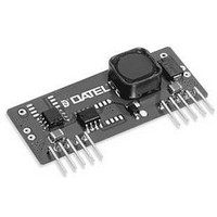
UNS-5/3-D12 Murata Power Solutions Inc, UNS-5/3-D12 Datasheet - Page 5

UNS-5/3-D12
Manufacturer Part Number
UNS-5/3-D12
Description
DC/DC Converter
Manufacturer
Murata Power Solutions Inc
Series
UNSr
Datasheet
1.UNS-53-D12.pdf
(5 pages)
Specifications of UNS-5/3-D12
Dc / Dc Converter O/p Type
Fixed
No. Of Outputs
1
Input Voltage
6V To 16.5V
Power Rating
15W
Output Voltage
5V
Output Current
3A
Supply Voltage
12V
Dc / Dc Converter Case Style
SIP
Output Power
15 W
Input Voltage Range
6 V to 16.5 V
Input Voltage (nominal)
12 V
Number Of Outputs
1
Output Voltage (channel 1)
5 V
Output Current (channel 1)
3 A
Package / Case Size
SIP
Lead Free Status / RoHS Status
Contains lead / RoHS non-compliant
The On/Off Control Pin
For normal operation, pin 5 should be left open. This pin has an internal
250kΩ pull-up resistor to +5V (or to +V
of the converters’ on/off functionality, a TTL logic high (+2.4V minimum,
+5V maximum or +V
enables the converter, and a quasi-TTL logic low (0 to +0.5V, 100μA max.)
Murata Power Solutions, Inc.
11 Cabot Boulevard, Mansfield, MA 02048-1151 U.S.A.
Tel: (508) 339-3000 (800) 233-2765 Fax: (508) 339-6356
www.murata-ps.com email: sales@murata-ps.com
Murata Power Solutions, Inc. makes no representation that the use of its products in the circuits described herein, or the use of other
technical information contained herein, will not infringe upon existing or future patent rights. The descriptions contained herein do not imply
the granting of licenses to make, use, or sell equipment constructed in accordance therewith. Specifications are subject to change without
notice.
T Y P I C A L P E R F O R M A N C E C U R V E S
Efficiency vs. Output Current and Input Voltage (Model UNS-5/3)
100
98
96
94
92
90
88
86
84
0
IN
0.5
maximum if +V
V
IN
= 16. 5V
5V Output Current (Amps)
1.0
V
IN
= 12V
IN
IN
< 5V, 100μA max.) applied to pin 5
if +V
1.5
IN
V
IN
< 5V). For dynamic control
= 6V
2.0
www.murata-ps.com
© 2008 Murata Power Solutions, Inc.
ISO 9001 REGISTERED
2.5
3.0
04/09/08
disables the converter. Control voltages should be referenced to pins 3 and 4
(–Input). For best results, use a mechanical relay or open-collector logic.
When the converter is turned off, its input "standby" current will be approxi-
mately 100μA. Applying a voltage that is greater than V
trol pin, or applying any voltage to this pin when no input power is applied to
the converter, may cause permanent damage to the converter.
USA:
Canada: Toronto, Tel: (866) 740-1232, email: toronto@murata-ps.com
UK:
France:
Germany: München, Tel: +49 (0)89-544334-0, email: munich@murata-ps.com
Japan:
China:
Efficiency vs. Output Current and Input Voltage (Model UNS-3.3/3)
100
98
96
94
92
90
88
86
84
Mansfield (MA), Tel: (508) 339-3000, email: sales@murata-ps.com
Milton Keynes, Tel: +44 (0)1908 615232, email: mk@murata-ps.com
Montigny Le Bretonneux, Tel: +33 (0)1 34 60 01 01, email: france@murata-ps.com
Tokyo, Tel: 3-3779-1031, email: sales_tokyo@murata-ps.com
Osaka, Tel: 6-6354-2025, email: sales_osaka@murata-ps.com
Website: www.murata-ps.jp
Shanghai, Tel: +86 215 027 3678, email: shanghai@murata-ps.com
Guangzhou, Tel: +86 208 221 8066, email: guangzhou@murata-ps.com
0
0.5
Technical enquiries email: sales@murata-ps.com, tel:
Non-Isolated, 3.3V & 5V, 3A DC/DC Converters
3.3V Output Current (Amps)
1.0
V
IN
V
= 13. 6V
IN
= 7. 5V
1.5
V
IN
= 4. 75V
MDC_UNS10-15W.B01 Page 5 of 5
2.0
UNS Series
IN
to the On/Off Con-
2.5
+1 508 339 3000
3.0


